 I had an idea for a cool project, but for it to work well, I needed some large 7-segment displays…like 3-4 inches tall. Unfortunately, the only ones I could find for sale on-line were absurdly expensive. I remembered seeing several folks make their own 7-segment displays, so that inspired me to try my hand at making my own.
Others have made seven segment displays out of such things as:
In all of the above, the light doesn’t look as well diffused as I’d like. You can see the points of where the LEDs are, or obviously see that the elements are lit at the ends. Also, the shapes are often quite crude. I want something that looks more professional (without going to the extent of making custom castings).
My mind wandered while I was at work, and I made this note to myself with how I should make these:
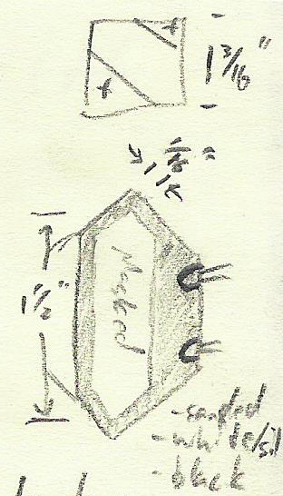
The (Rough) Plan
If you can’t read my handwriting (I don’t blame you, I can’t either half the time), the elongated white hexagon says “Masked” in it, and the bullet points say this:
- sanded
- while/sil (didn’t have enough room to write silver)
- black
The basic idea is that I’ll:
- cut a square of acrylic 1 3/16” on a side
- cut off the 2 corners to make a hexagon
- sand all the surfaces to a matte finish (to diffuse the light best)
- mask off the display segment itself (we need somewhere for light to shine through)
- paint it white (to encourage internal reflection)
- paint it black (for contrast)
- peel off the mask
- add LEDs in the wide painted part (to reduce bright spots right at the LEDs)
I came up with this idea because it only required the tools (and materials) that I already had on hand:
- 1/4 inch acrylic (i.e. plexiglass)
- chop saw
- hand sander
- drill
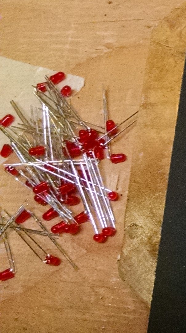
Additionally, I ordered a bunch of 3mm LEDs from digikey.com. If I did it again, I might have selected slightly brighter LEDs, but these worked out OK.
The Prototype
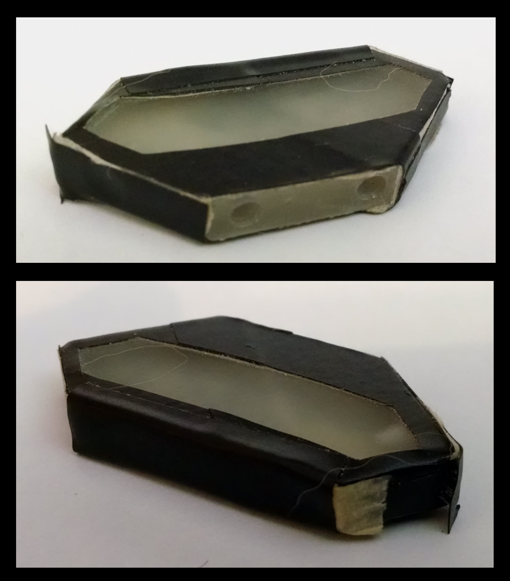
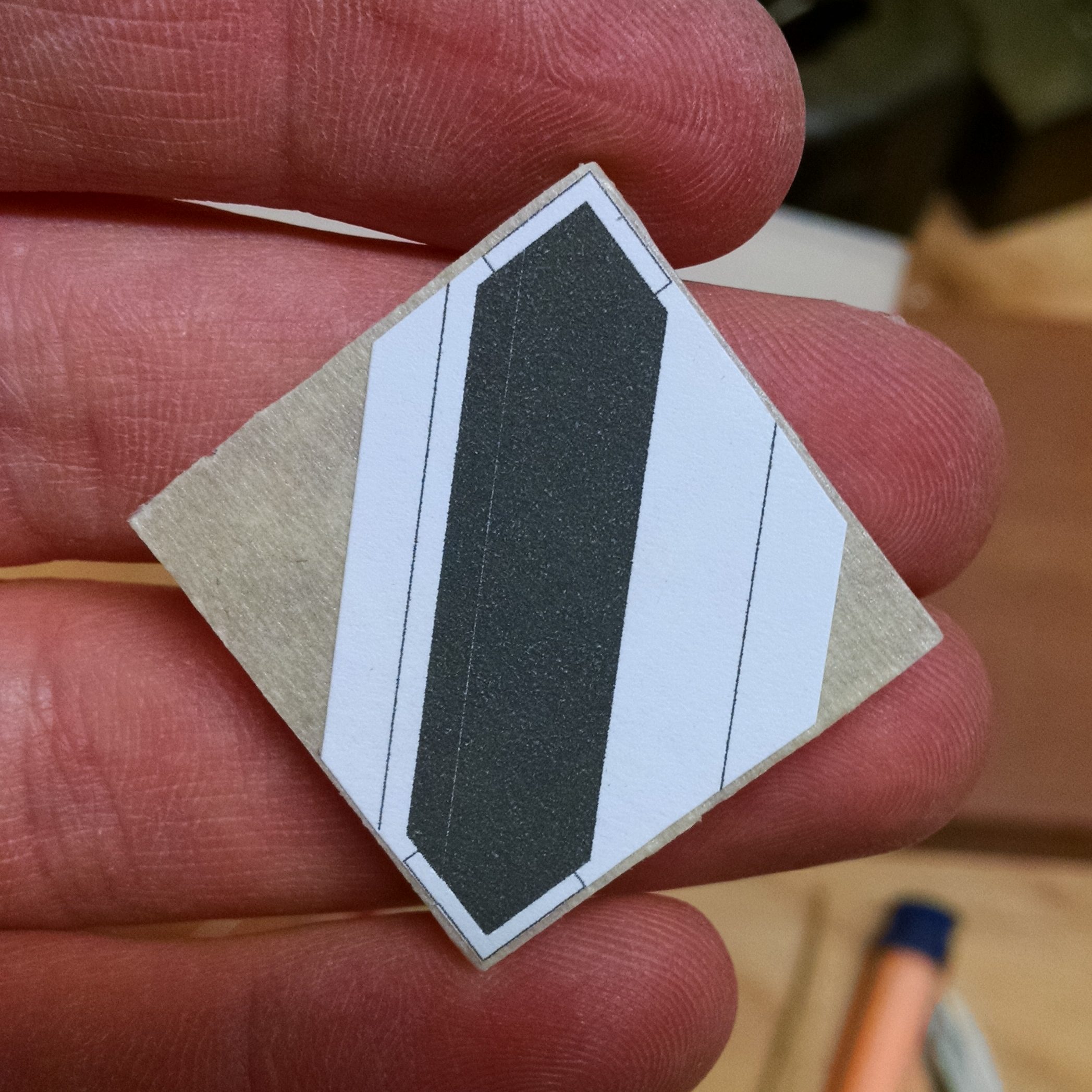
A bit later, I decided to make a single quick-and-dirty prototype to make sure that the idea worked. Instead of messing with paint, I just used masking tape (for white) and electrical tape (for black):
I was pleased to find that it worked as well as I had hoped it would! (But of course, I didn’t take any photos of it lit up).
So, without any further ado, here’s the How-To:
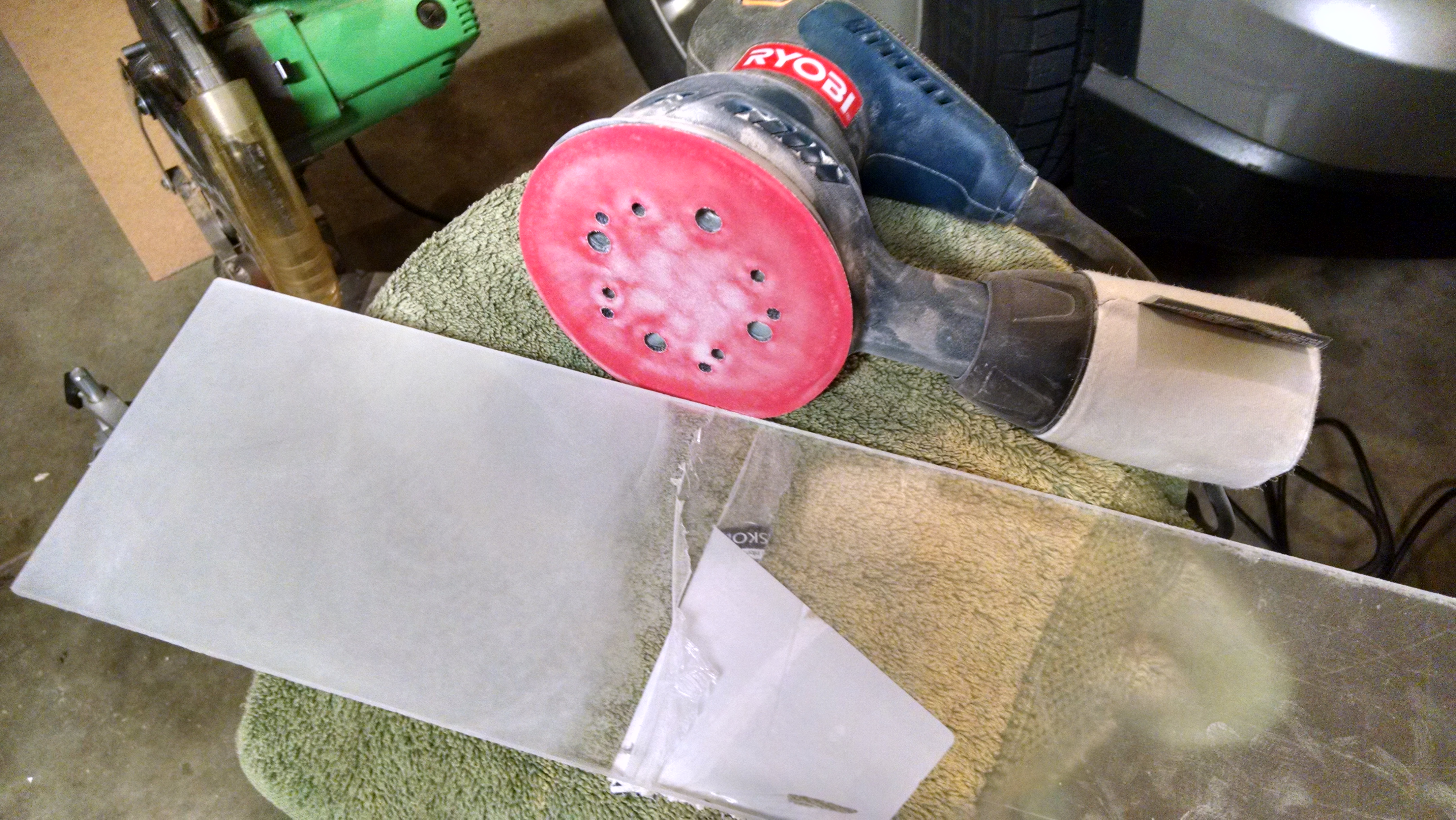
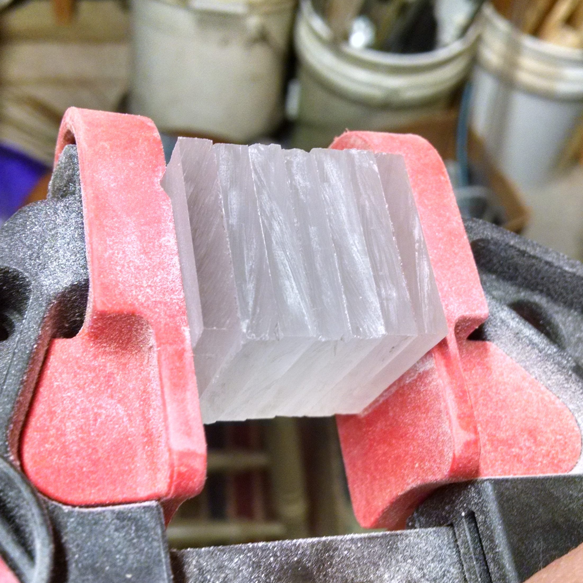
Start with a nice, clear, unblemished piece of acrylic…
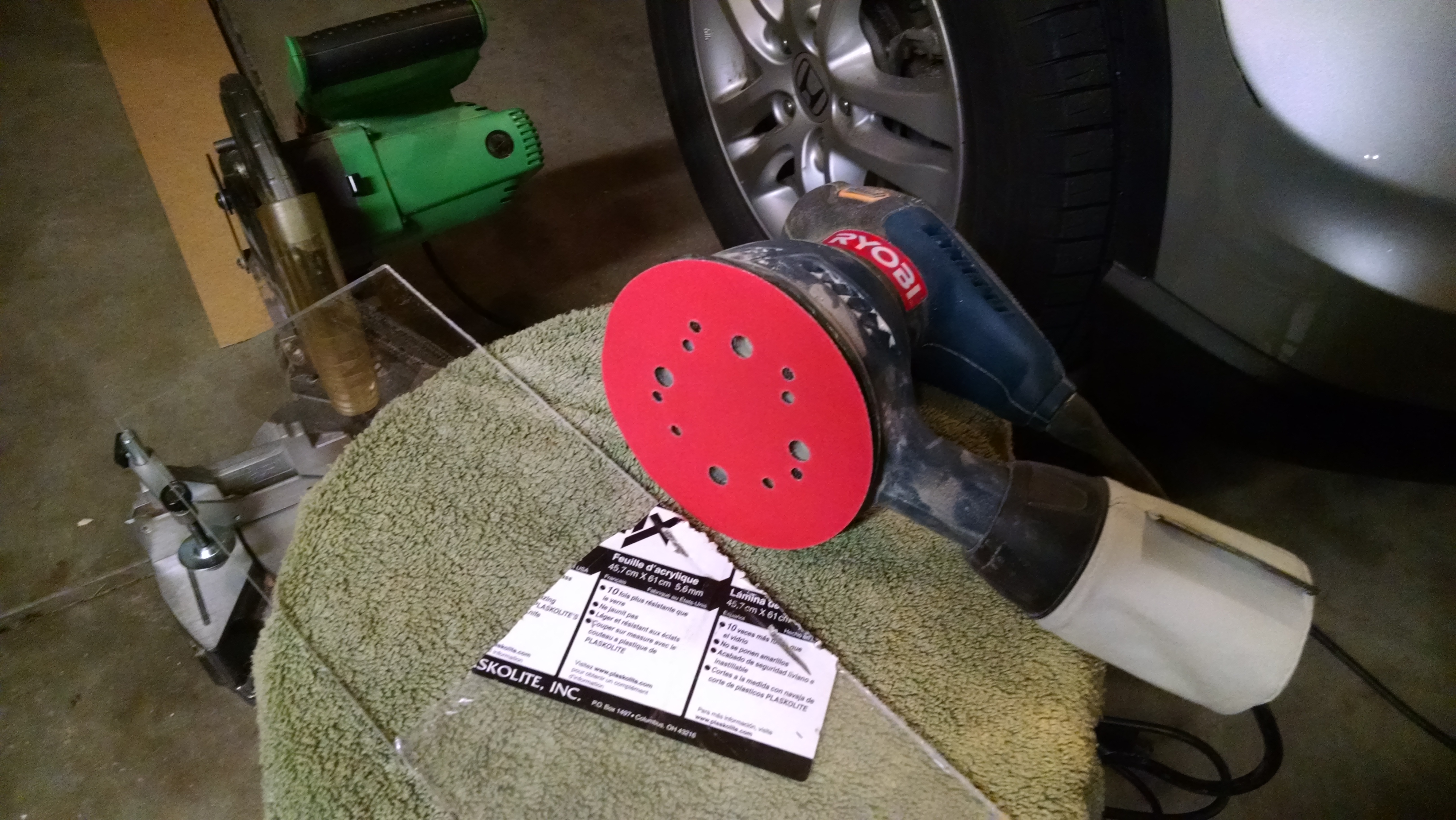
…And sand it to a matte finish. I used 220 grit sandpaper (because it’s what I had). It seemed to work well…I didn’t have to sand for too long, and it didn’t leave too many obvious scratch marks.
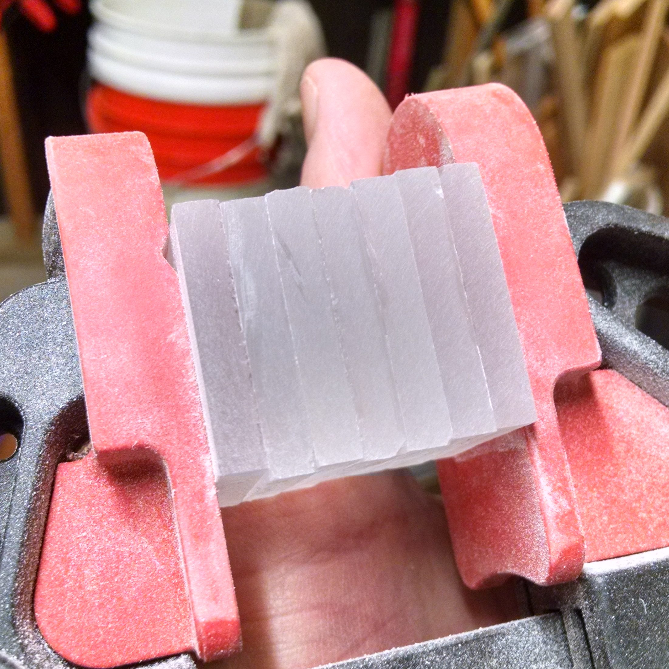
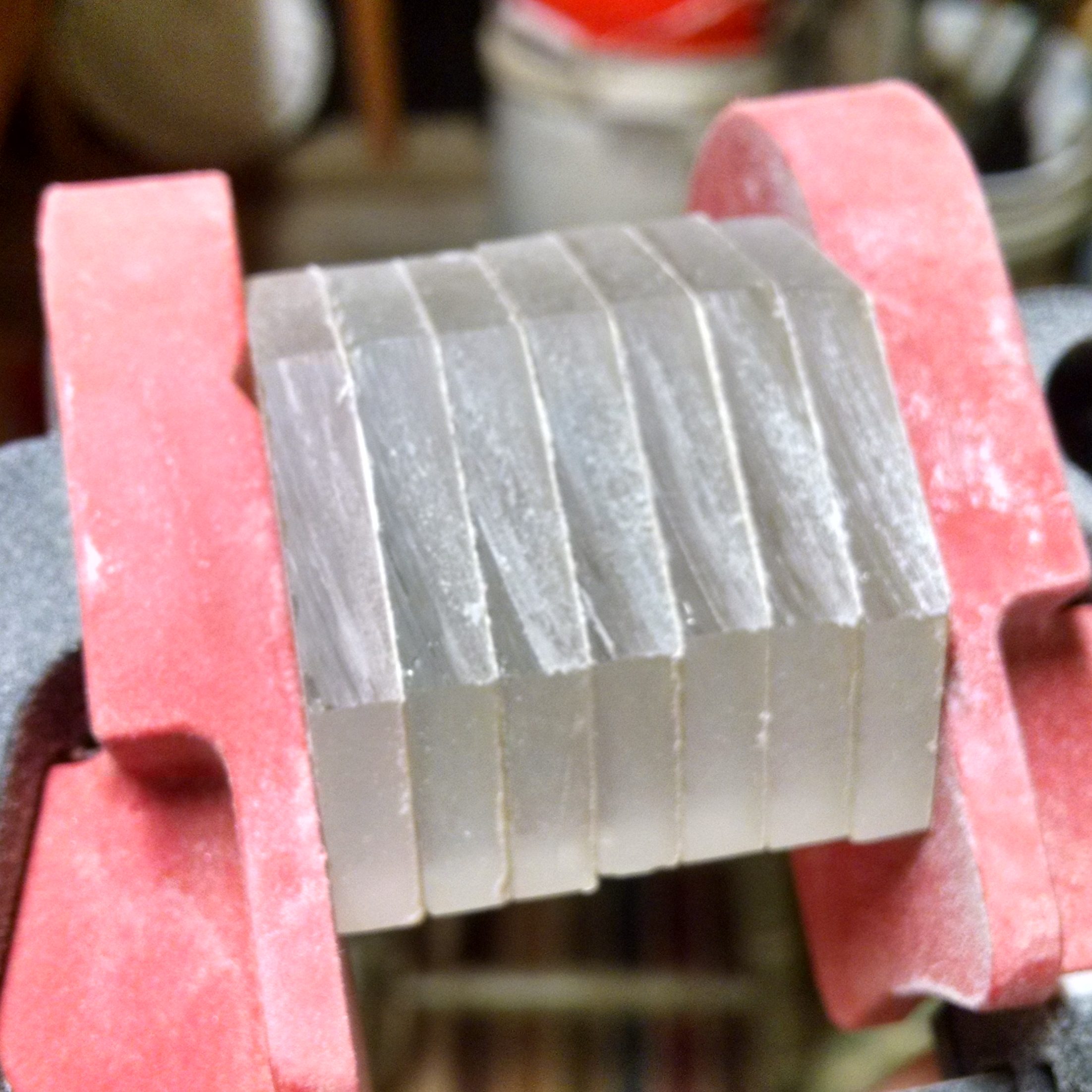
Next, cut strips 1 3/16 inches wide. As you can see, I clamped some wood to my chop saw as a stop to make it easier to consistently cut the same size. I test-cut a piece of wood to make sure the stop was in the right place. I used a somewhat fine-toothed blade to cut the acrylic, but it still managed to melt as it was cutting and leave stuff by the cut. Some melted plastic also stuck to the blade, but that didn’t seem to affect anything.
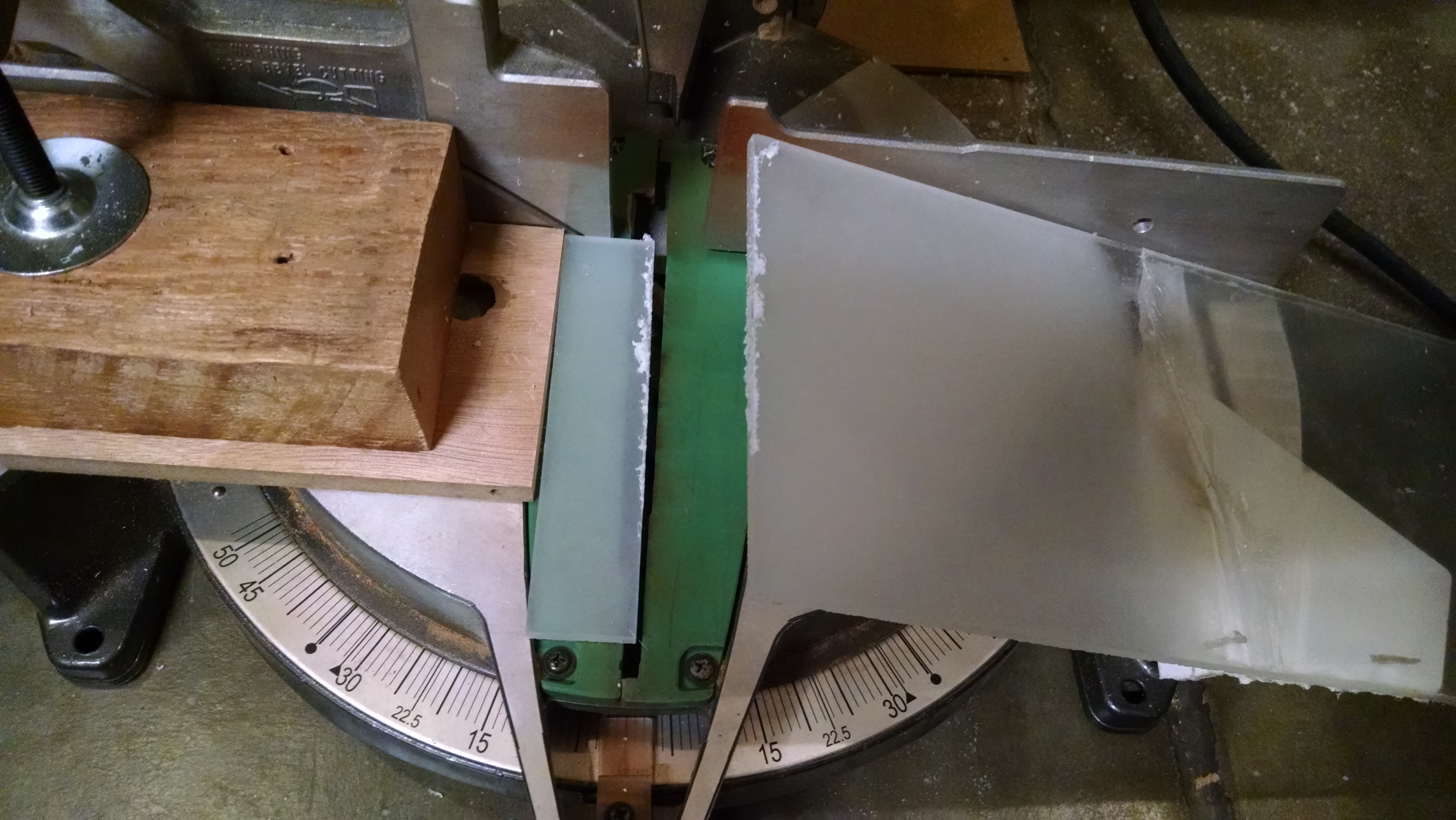
It was easy to pick the melted stuff off, and the resulting cut looked okay.
Leaving the stop where it is, cut each strip into several squares. The pieces will want to rotate into the blade, especially on a saw like mine where there’s a big gap in the fence. I tried to reduce this by holding the square in place with another piece of wood. Be very careful when doing this!!!
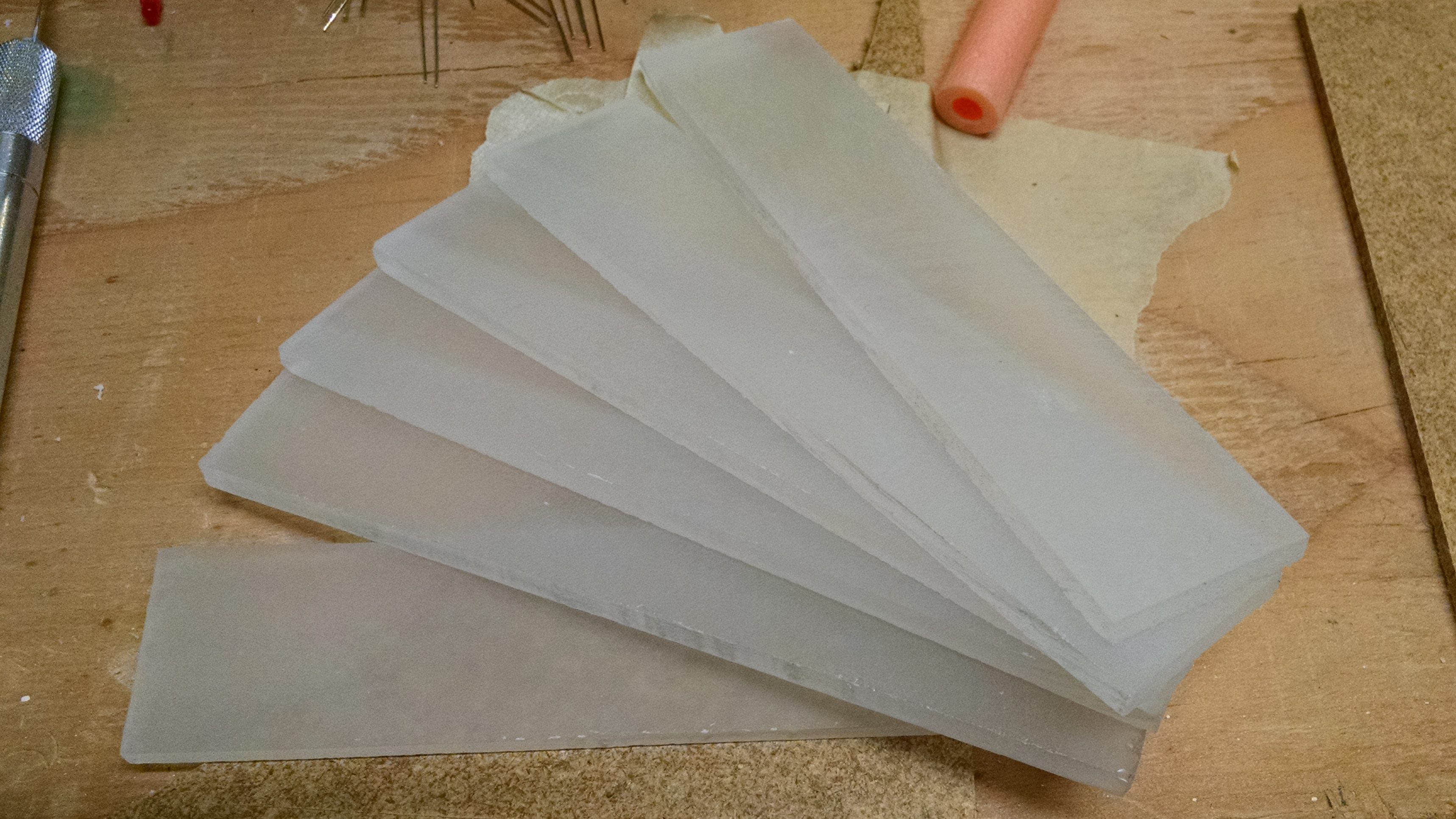
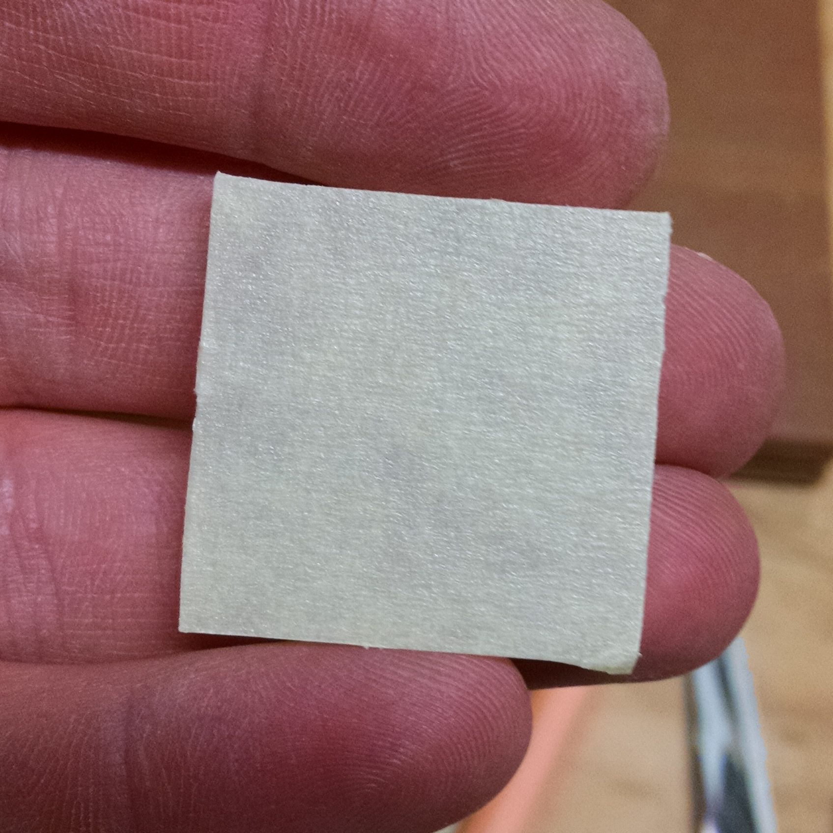
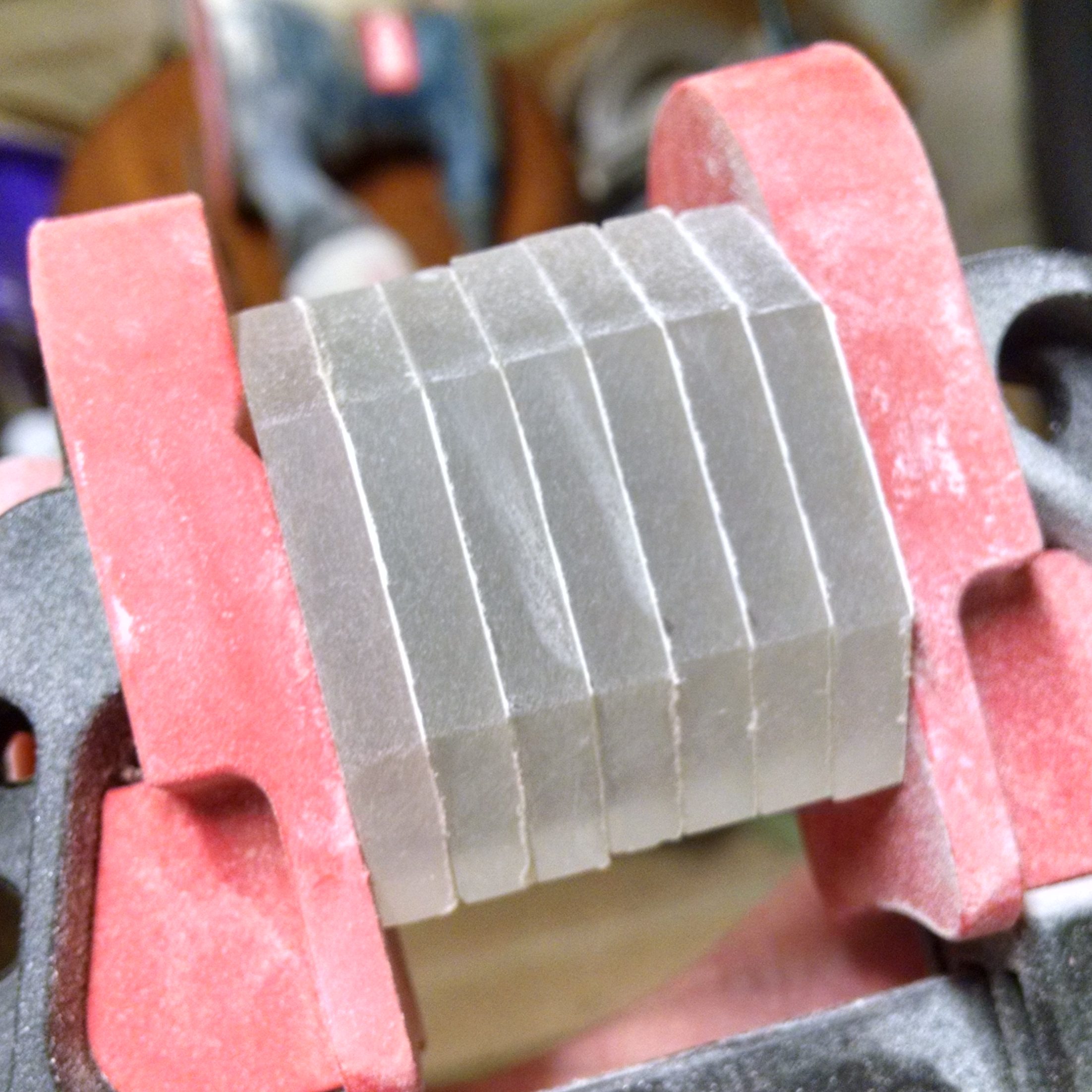
You should now have a bunch of (mostly) square pieces of acrylic.
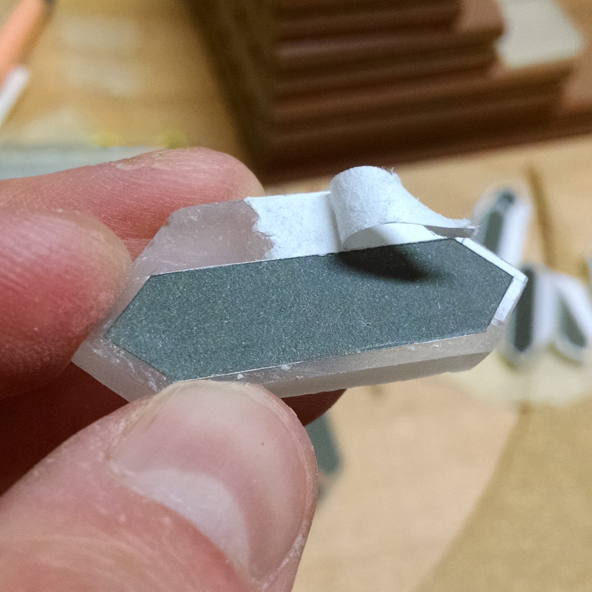
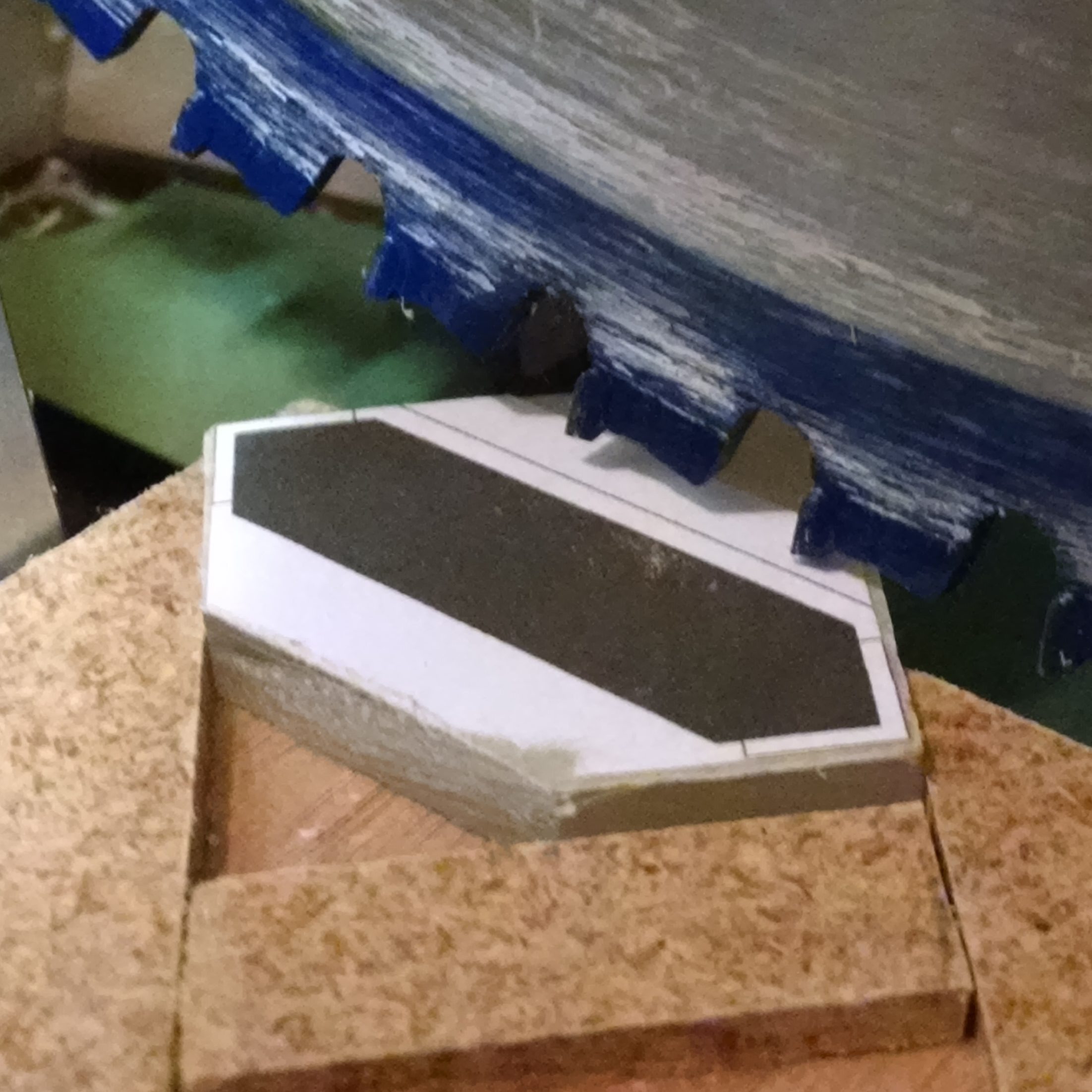
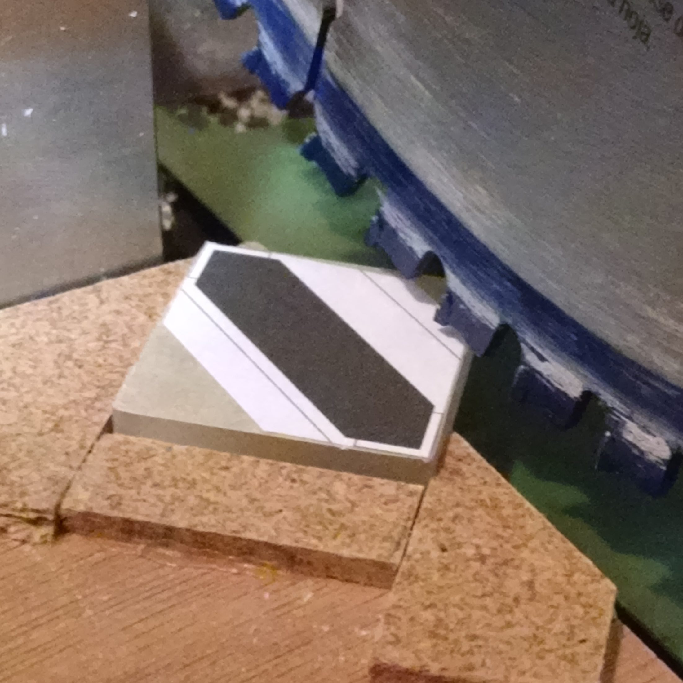
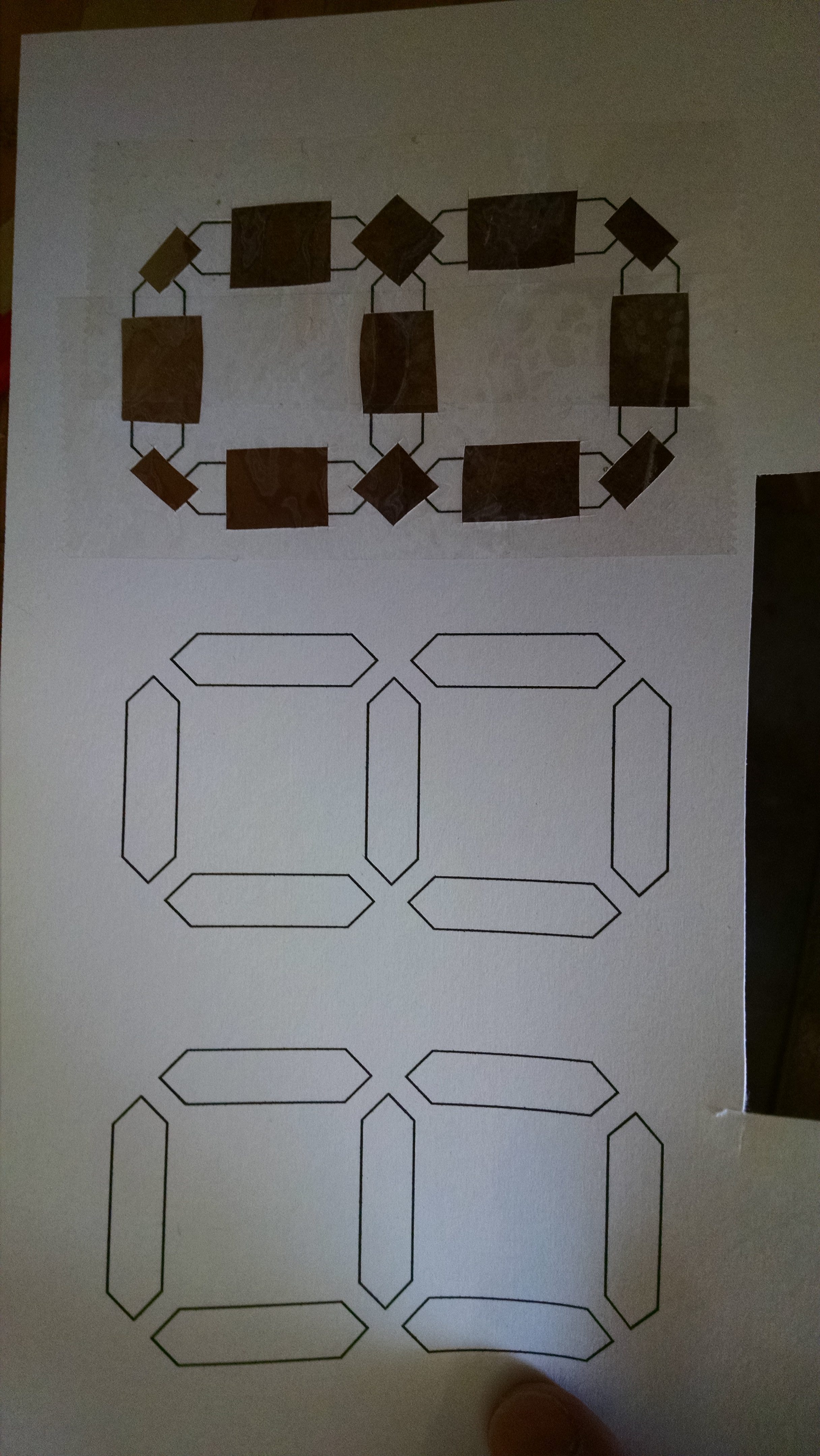
Next, you’ll apply the mask to each piece. Put masking tape on one side of the square, and trim off the excess.
I printed out a pattern on some printing labels to make placing and cutting a consistent mask easier. You can use this link to download the label templates (in OpenOffice format) that I used. I printed them on Avery 8160 Address labels. Once you’ve peeled one off, trim the excess…
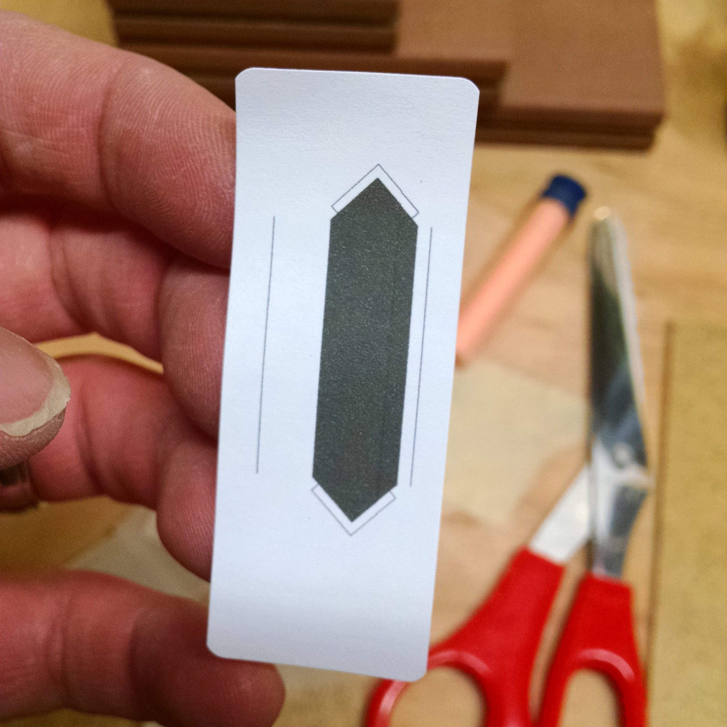
…And place it over the masking tape, trying to center it on the square. If your square isn’t perfect (e.g. one cut got pulled into the saw a bit), try putting that corner on the left in the photo below (because we’ll cut more of that corner off).
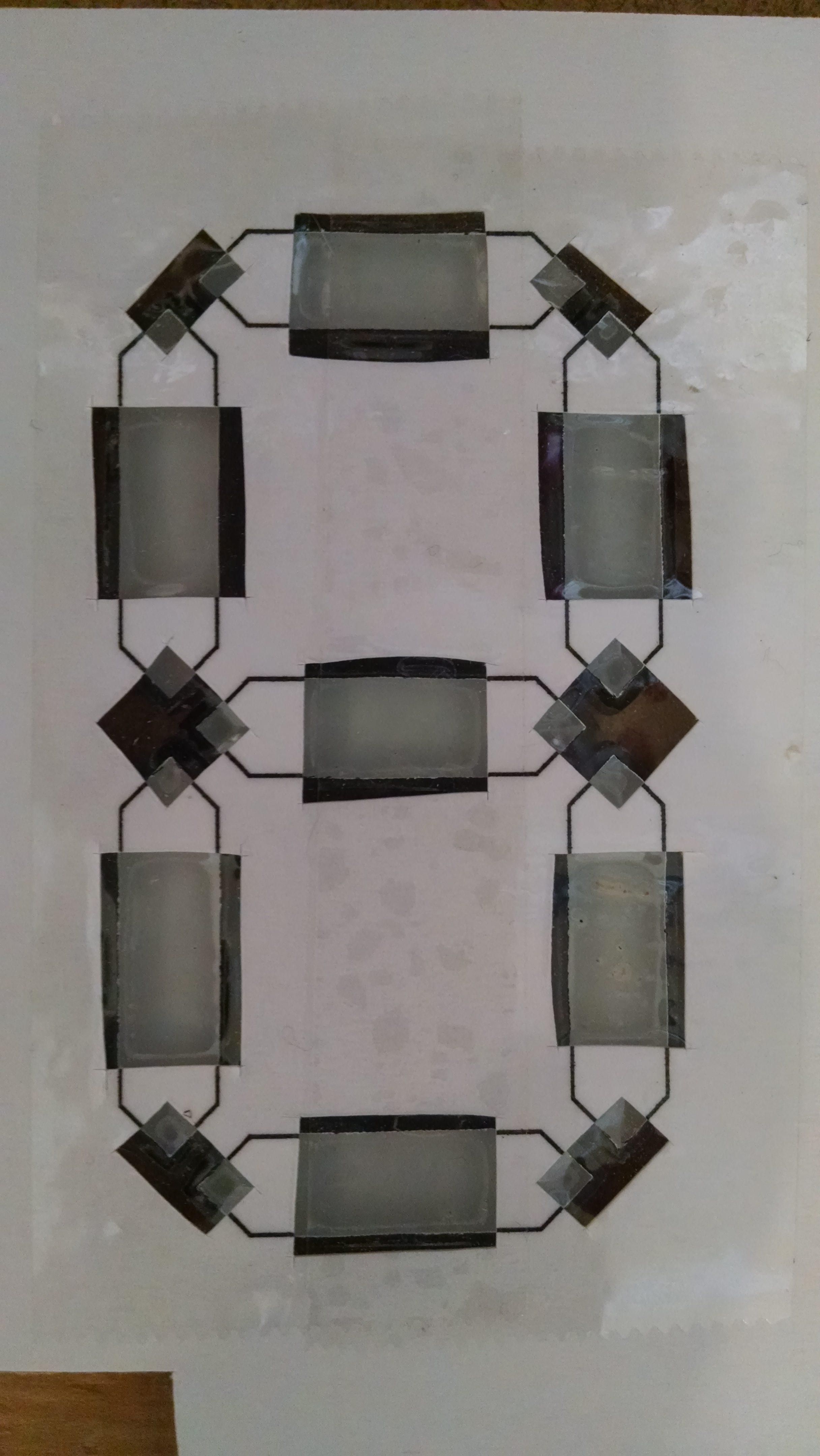
The masking tape is actually pretty important. I tried one piece without the masking tape, and found that the label doesn’t come off very well:
This part probably isn’t necessary, but sometimes I’m a perfectionist in odd ways. I sanded the edges of the squares to remove any saw marks. To do this, I clamped a few squares together, and went at it with my hand sander. A disk sander would have been a much better tool for this job.
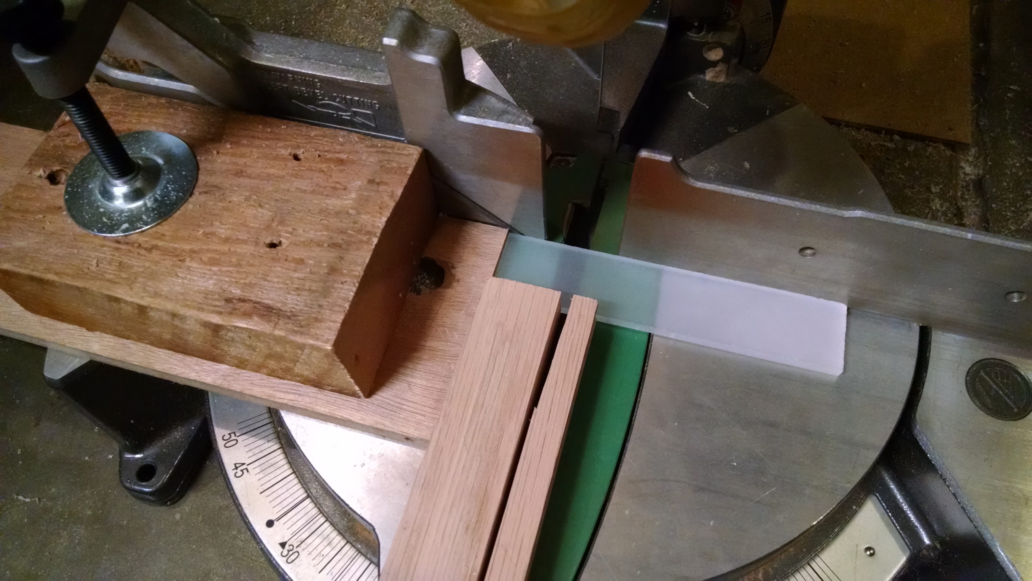
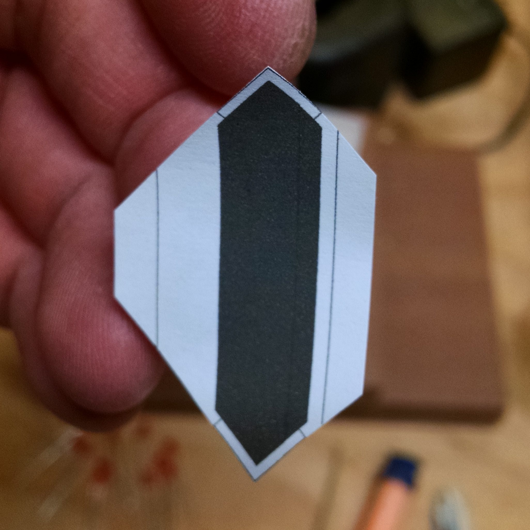
Next step is to cut off the corners of the squares to create the hexagon shape we’re looking for. The lines on the labels I printed out are approximately where I want the cuts to be made. I created a jig to help with this step by gluing some strips of wood onto a board at a 45 degree angle. I can clamp this board onto my chop saw to easily hold the acrylic squares in the right position. I did hold the pieces in the jig by hand…again, be very careful! The chop saw can’t tell the difference between the acrylic and your finger!
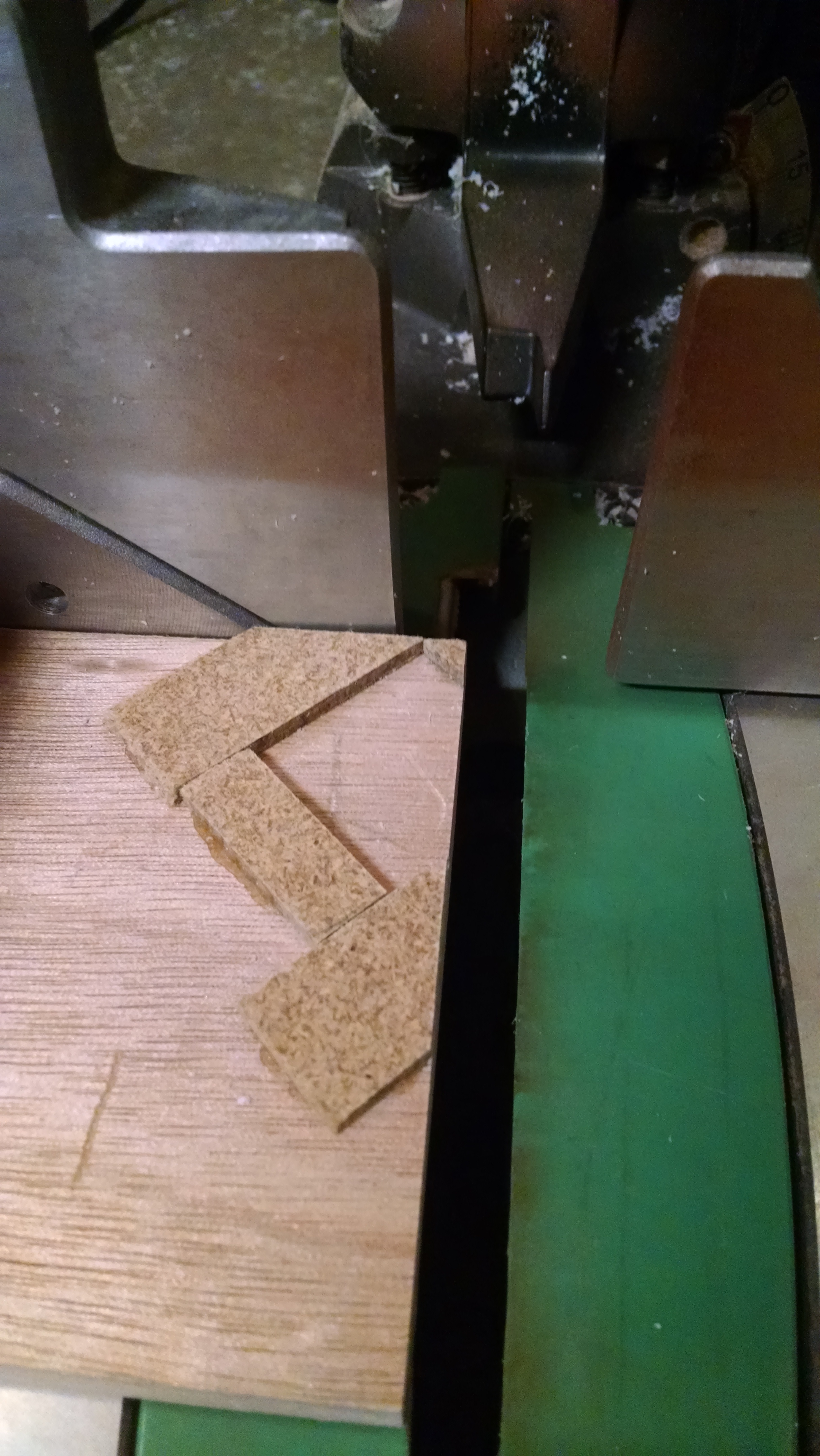
Again, it’s probably unnecessary, but I decided to sand the newly-cut edges:
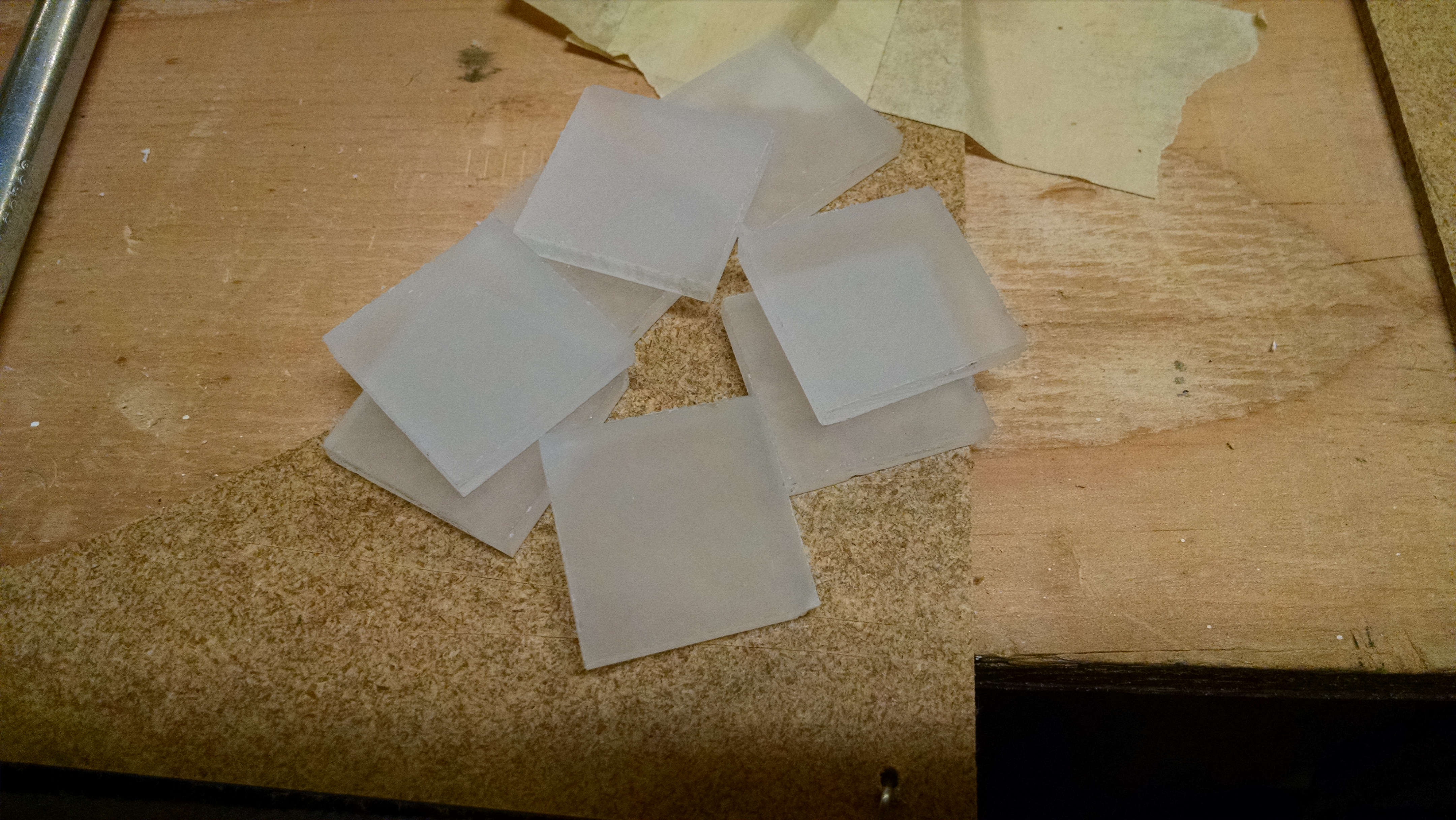
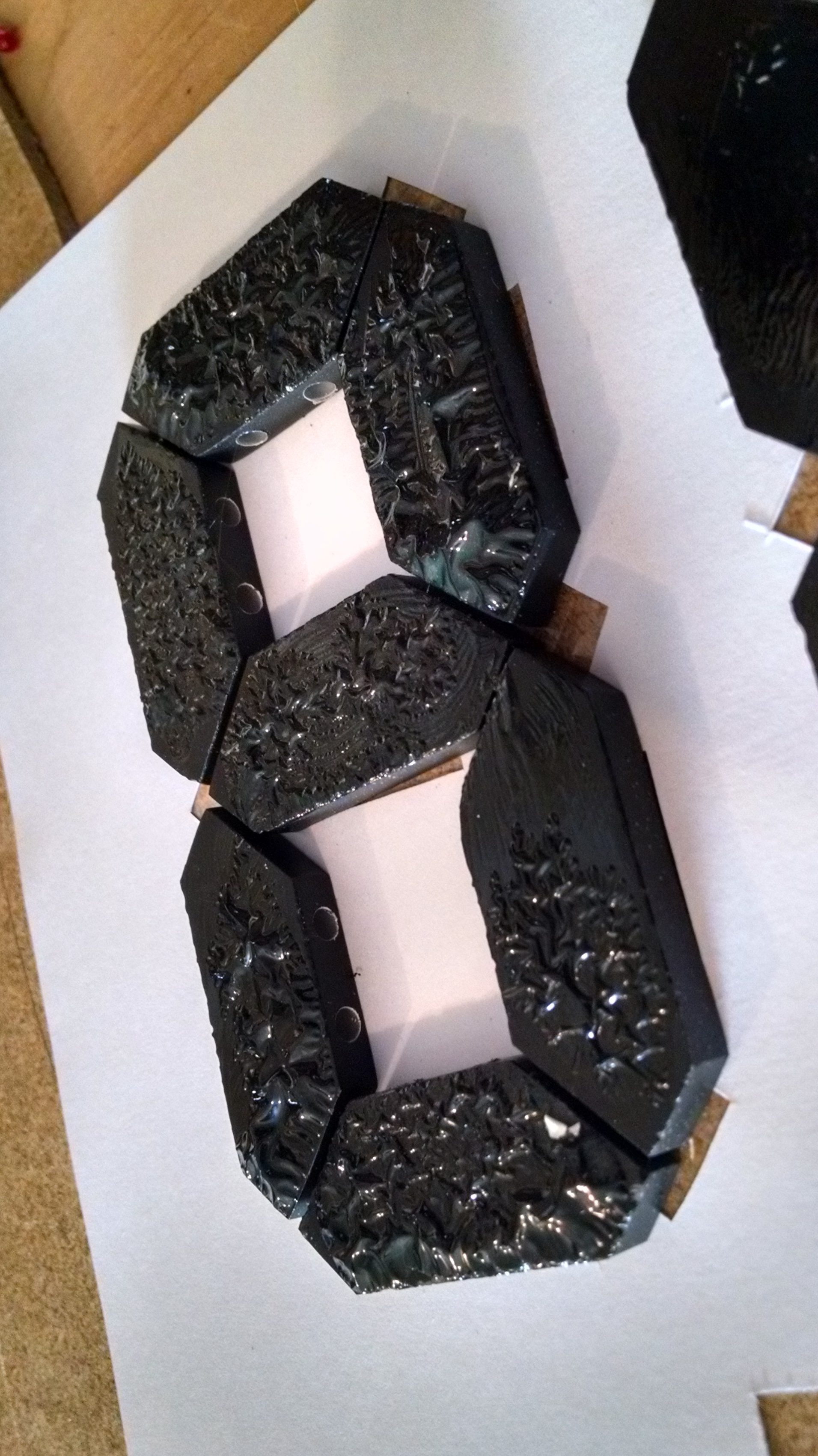
And now, you should have a nice collection of acrylic hexagons:
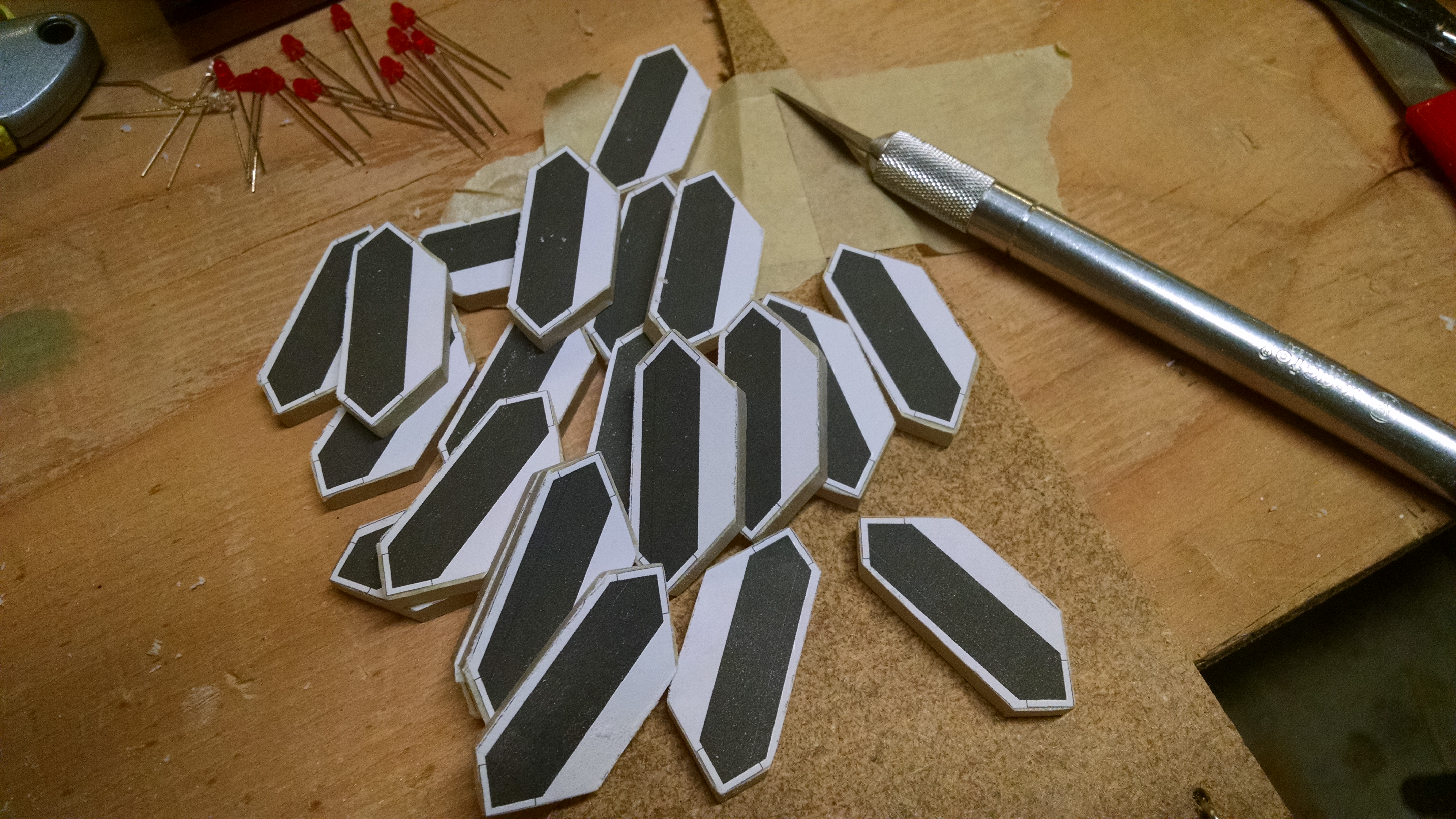
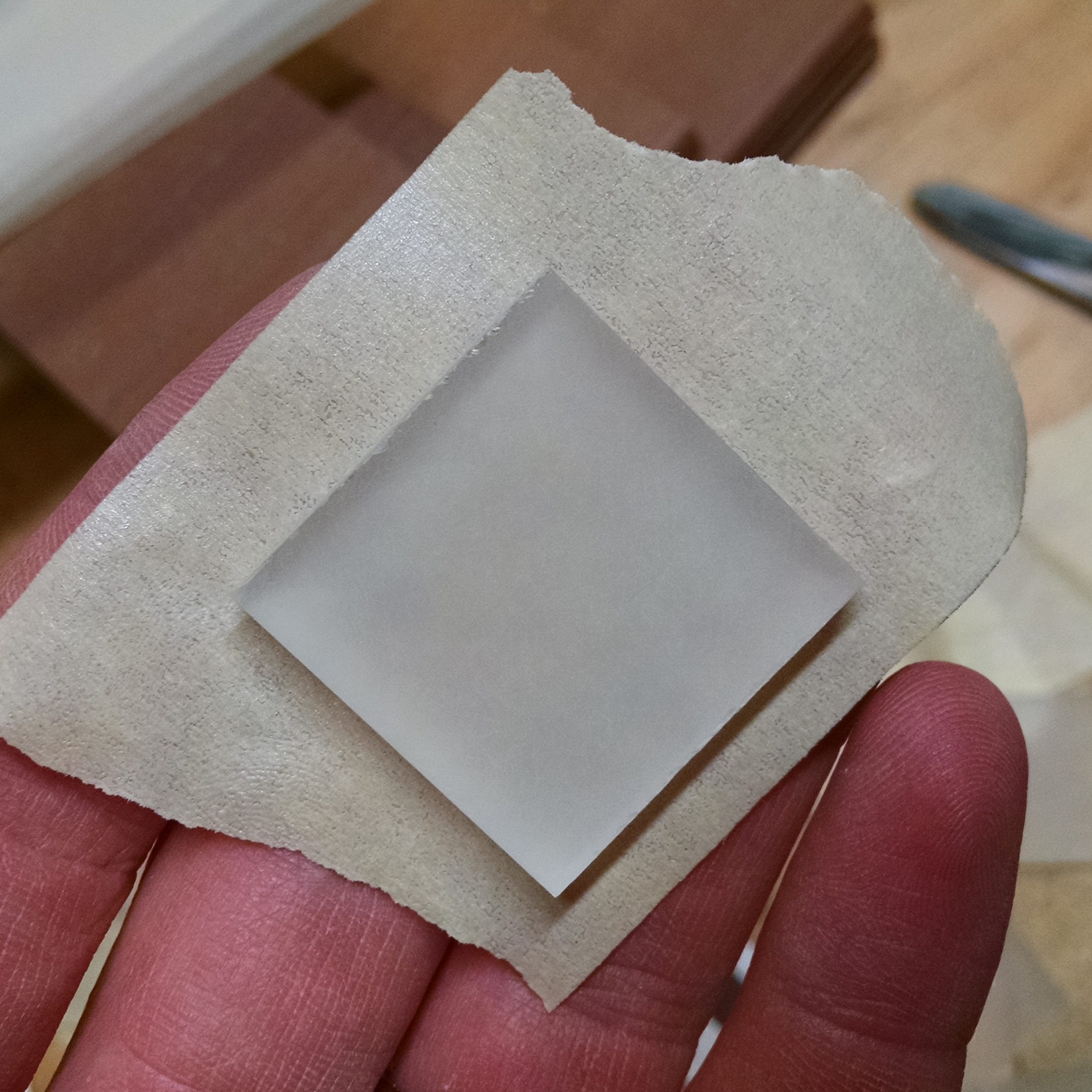
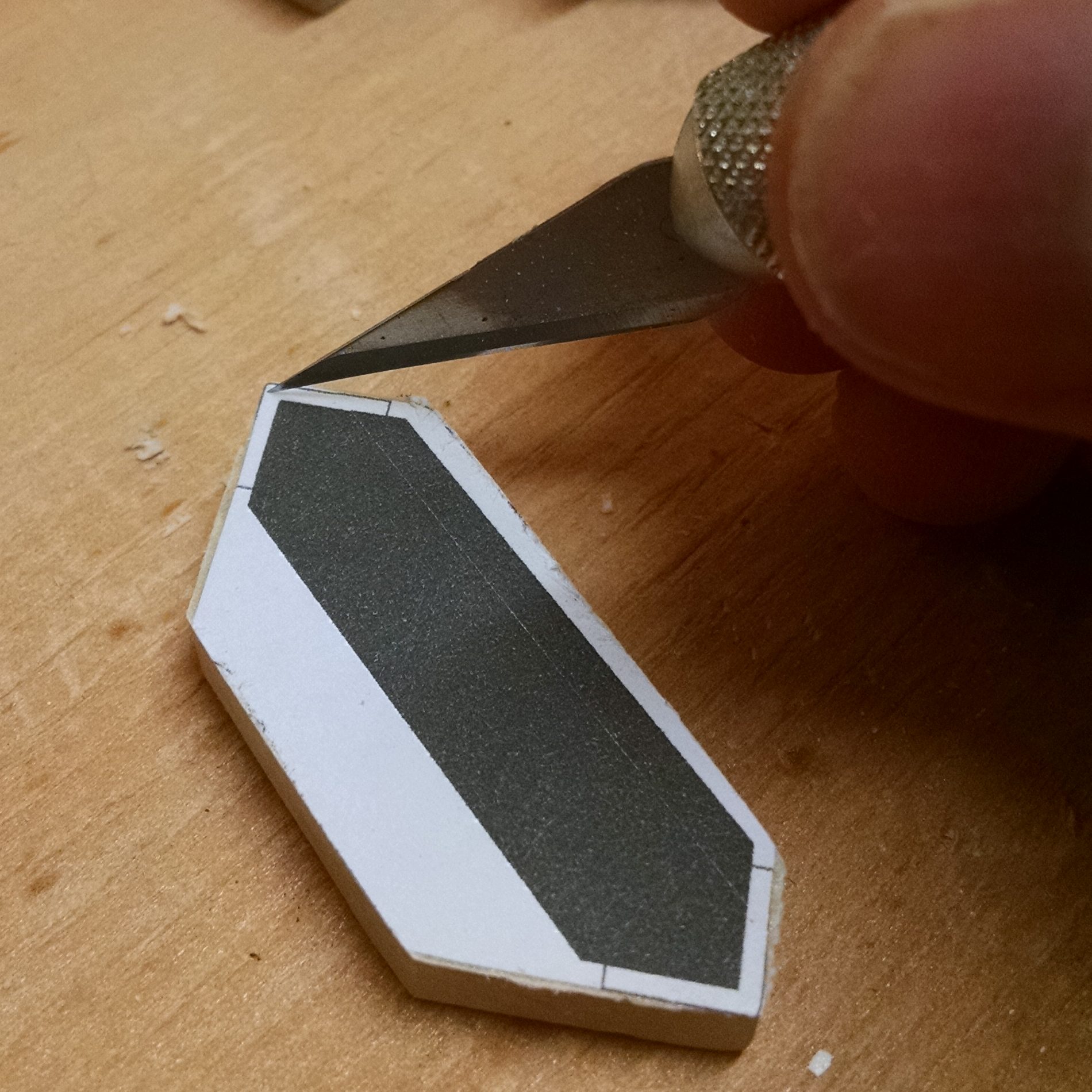
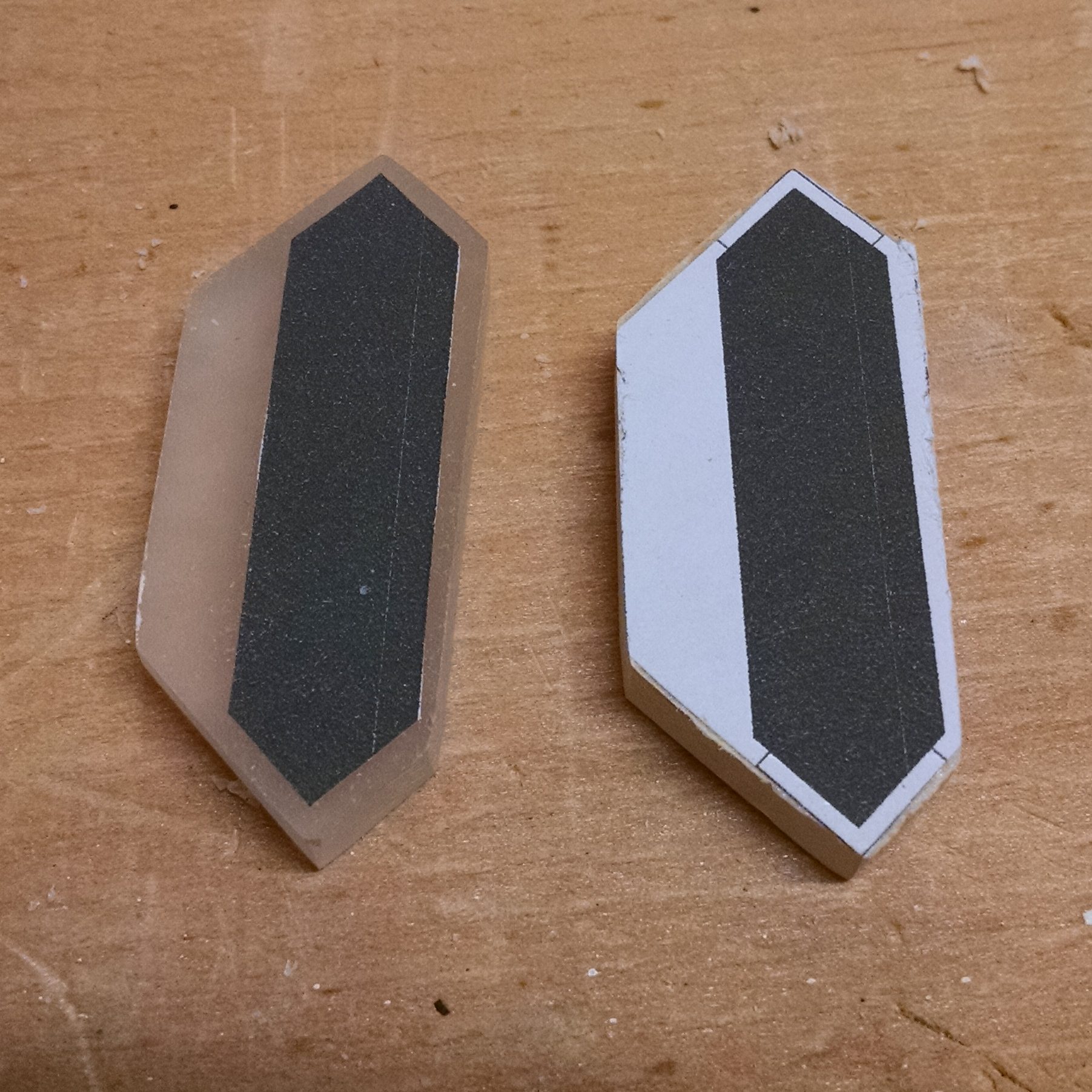
Now, you’ll need to cut around the mask and peel off the excess. I used an X-ACTO knife, but a utility knife or razor blade would work fine, too. Using a straightedge may help, but cutting freehand worked well for me.
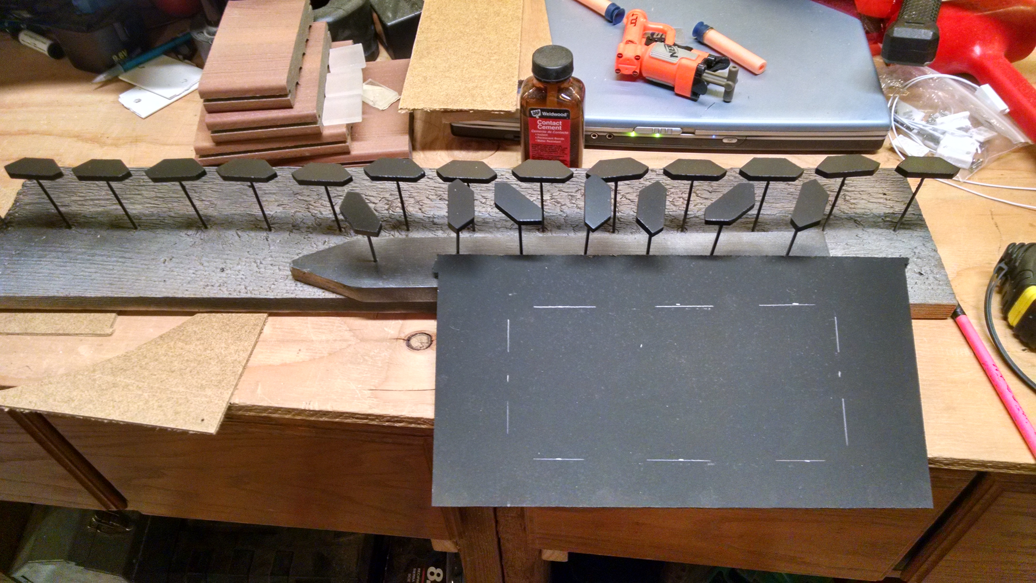
We want to paint the exposed areas now. I didn’t want to waste time painting one side at a time and waiting for it to dry in between, so I hot-glued toothpicks to the mask (thanks for the idea, Jenna!)…
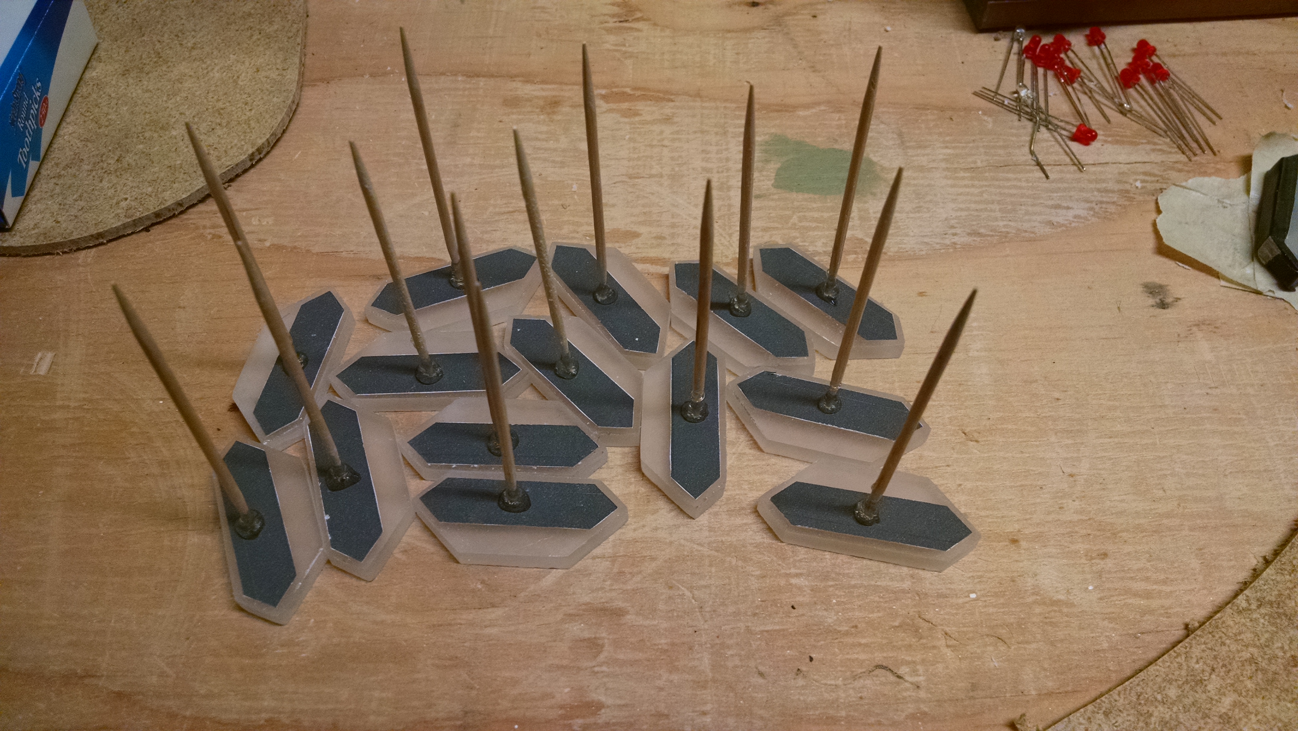
… then stuck the toothpicks into holes I drilled in a piece of wood.
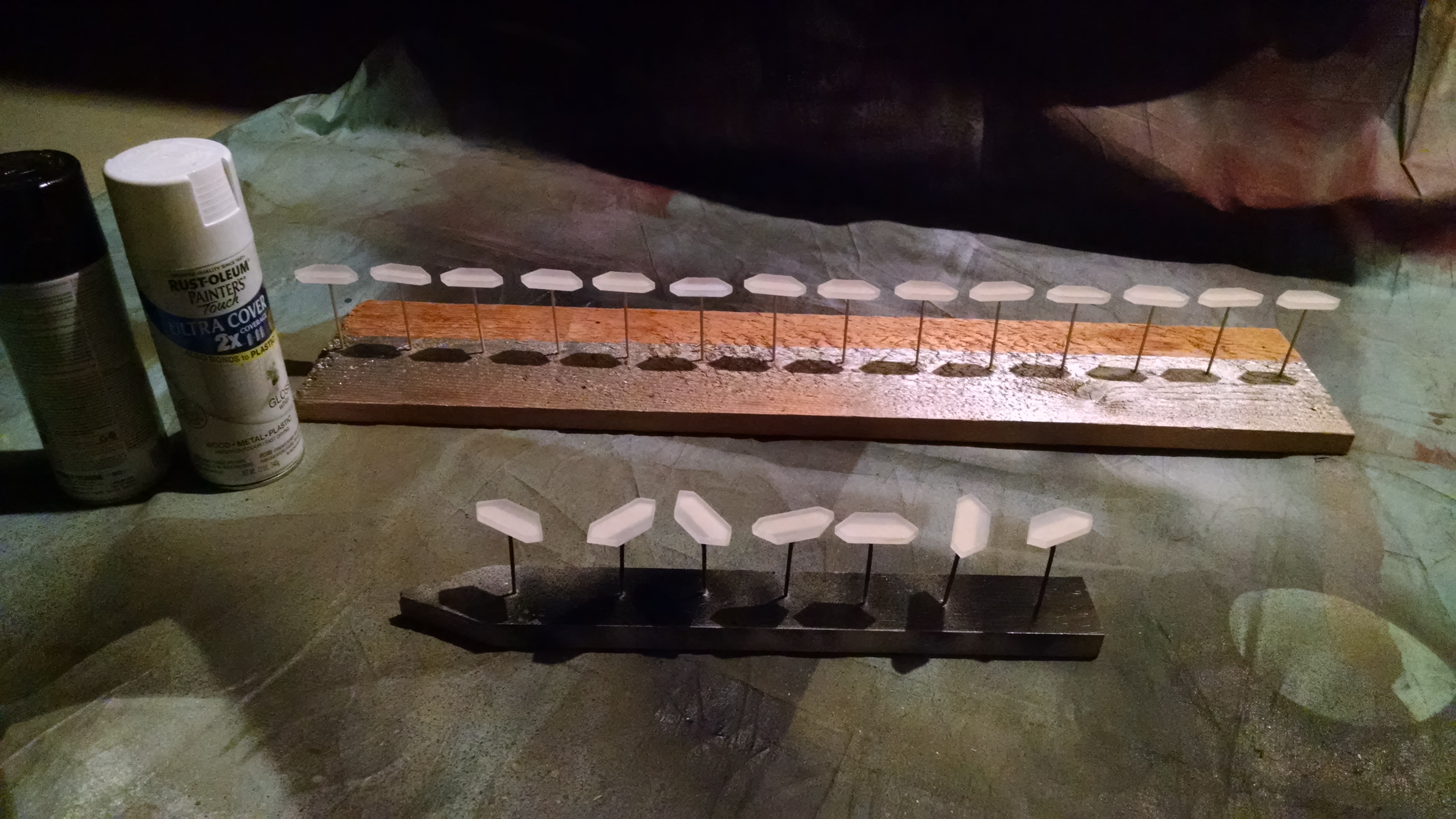
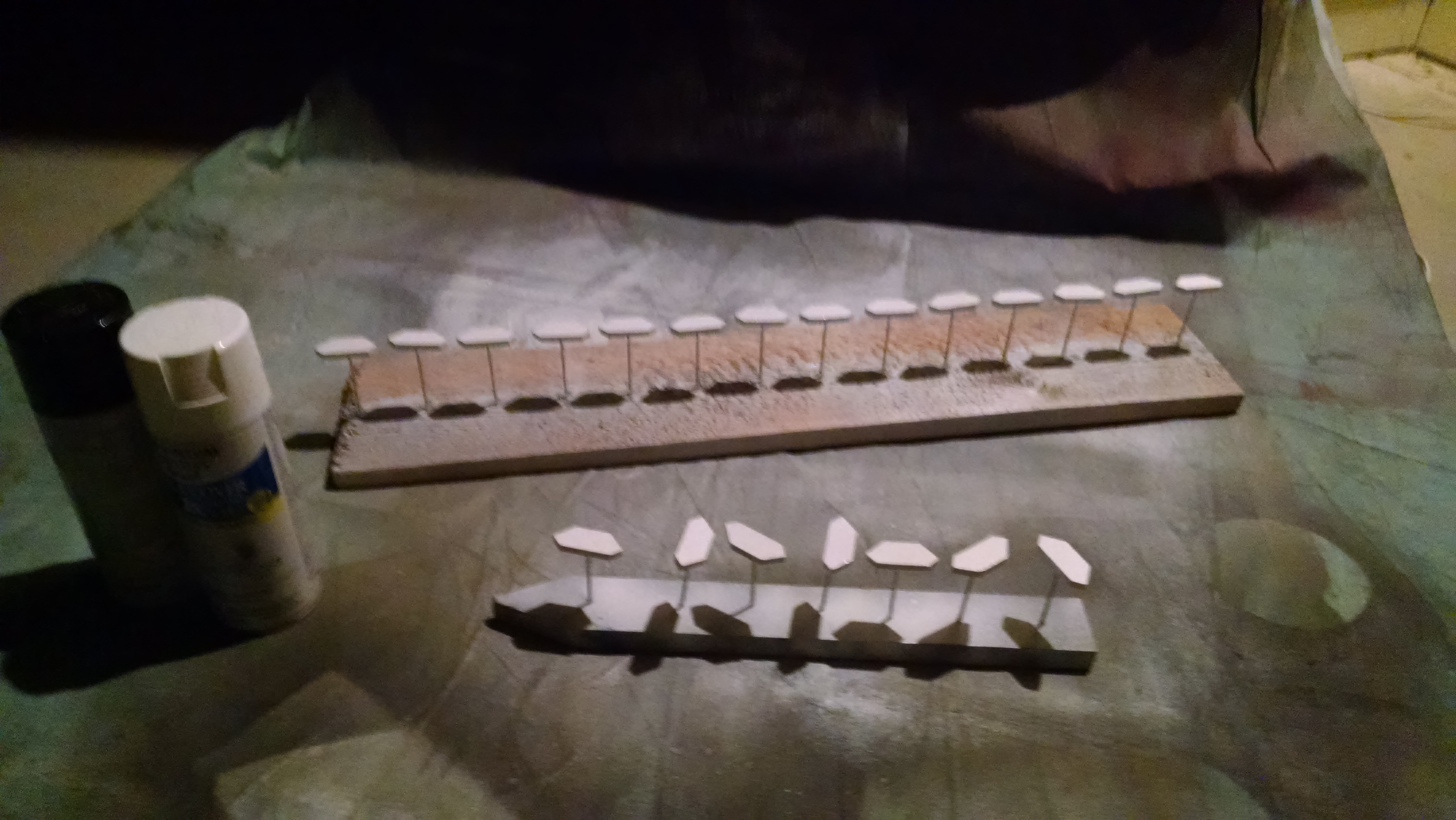
First, a coat of white paint, then black after it dries. While I was doing the coat of black, I went ahead and painted the board that I will attach the segments to (and penciled in the edges of where I want the digits).
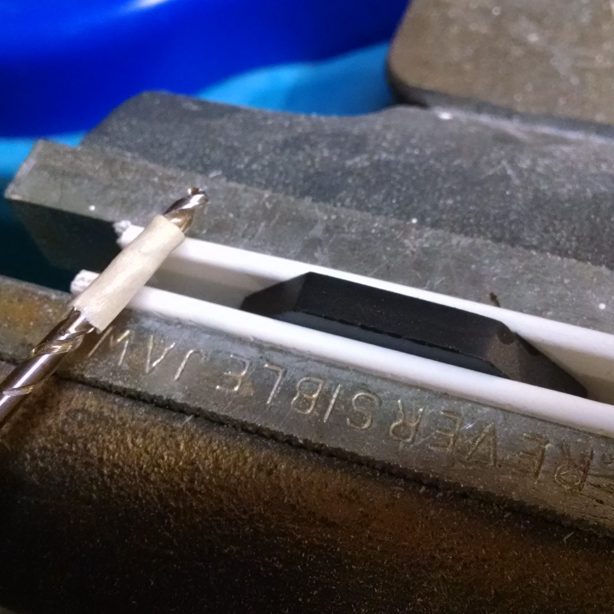
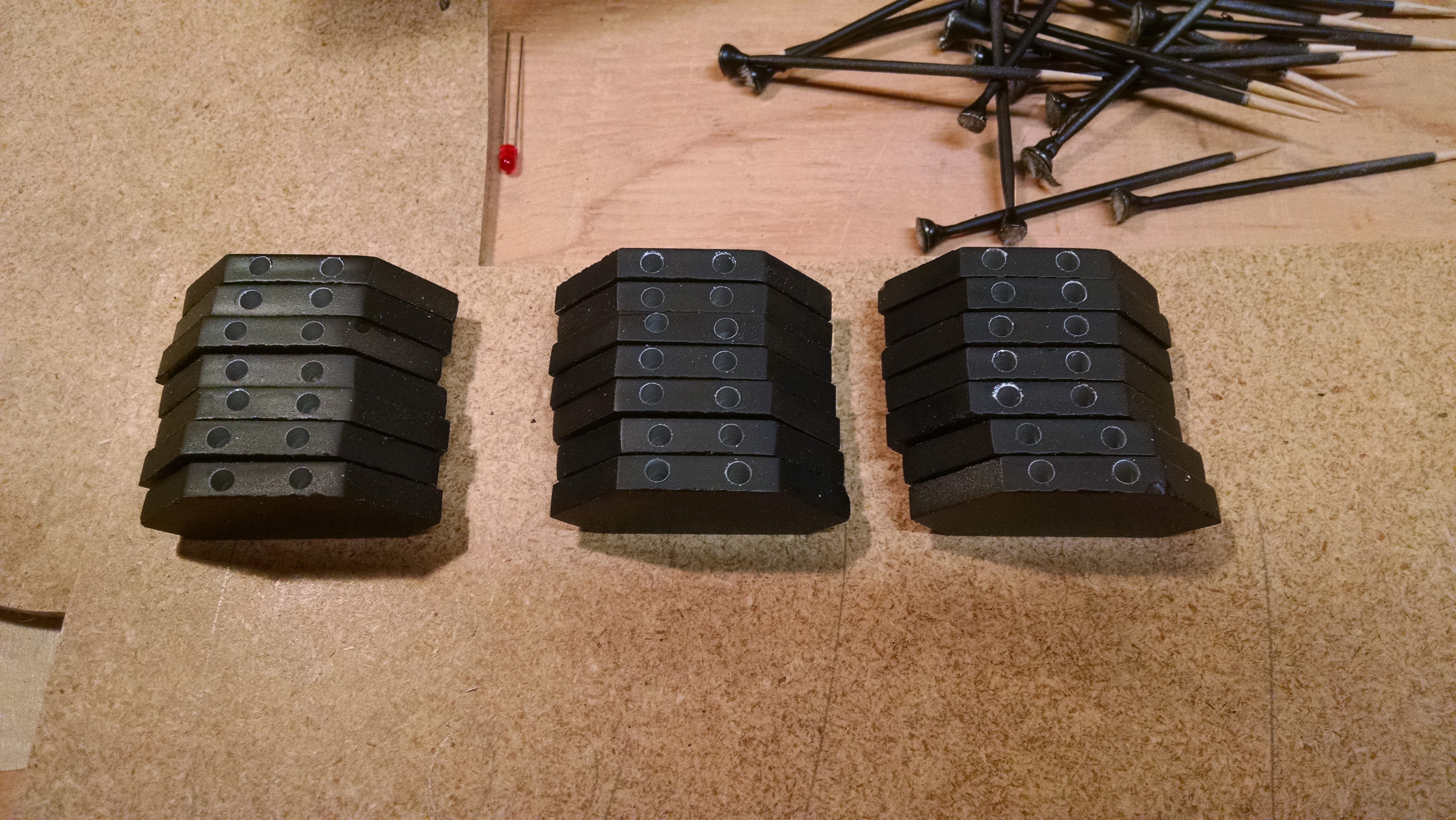
Once the paint is finally dry, remove the toothpicks, and drill the holes for the LEDs. The holes go in the edge of the hexagon that is most covered by paint (i.e. the edge where we cut less of the corner off the square). I’m using 3mm LEDs, so I need a hole at least that large. Unfortunately, I don’t have metric drill bits, so I settled for 1/8th inch (7/64th isn’t quite large enough). Some websites will recommend using a drill bit for ceramic/glass to get a clean hole. While a ceramic bit certainly works, it drills much more slowly, and I don’t think it produced a better hole than a standard bit. (Perhaps a ceramic bit prevents chipping if you drill all the way through?)
You don’t want to drill too deep, otherwise you’ll see a bright spot. I used a piece of masking tape on the bit so I could gauge depth. Also, you don’t want to drill too close to the end. Since these will be arranged together in a square, there won’t be quite enough room close to the corners. I drilled about 1/8th inch from each end.
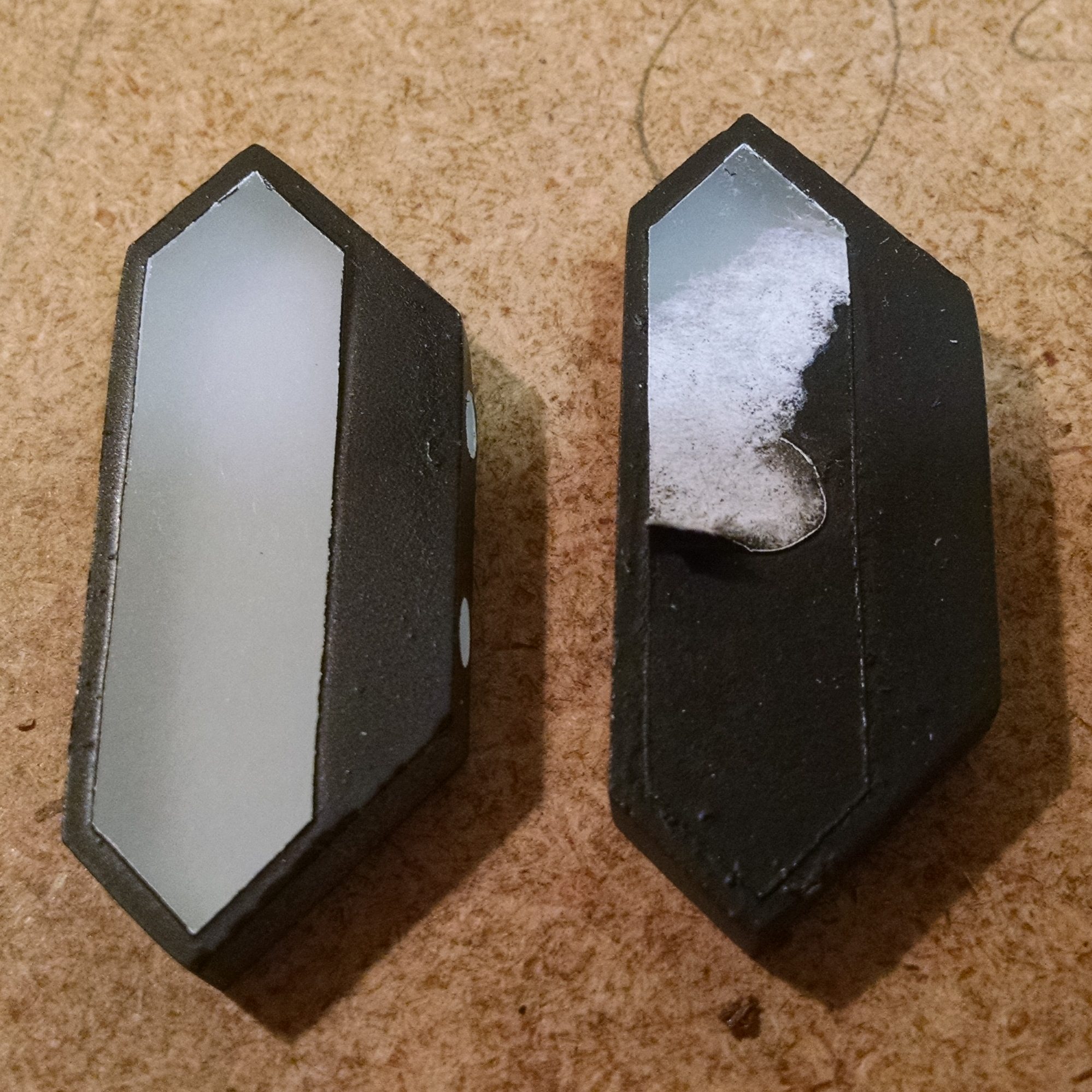
Now, you can peel off the masks and really get a sense of what the finished product will look like!
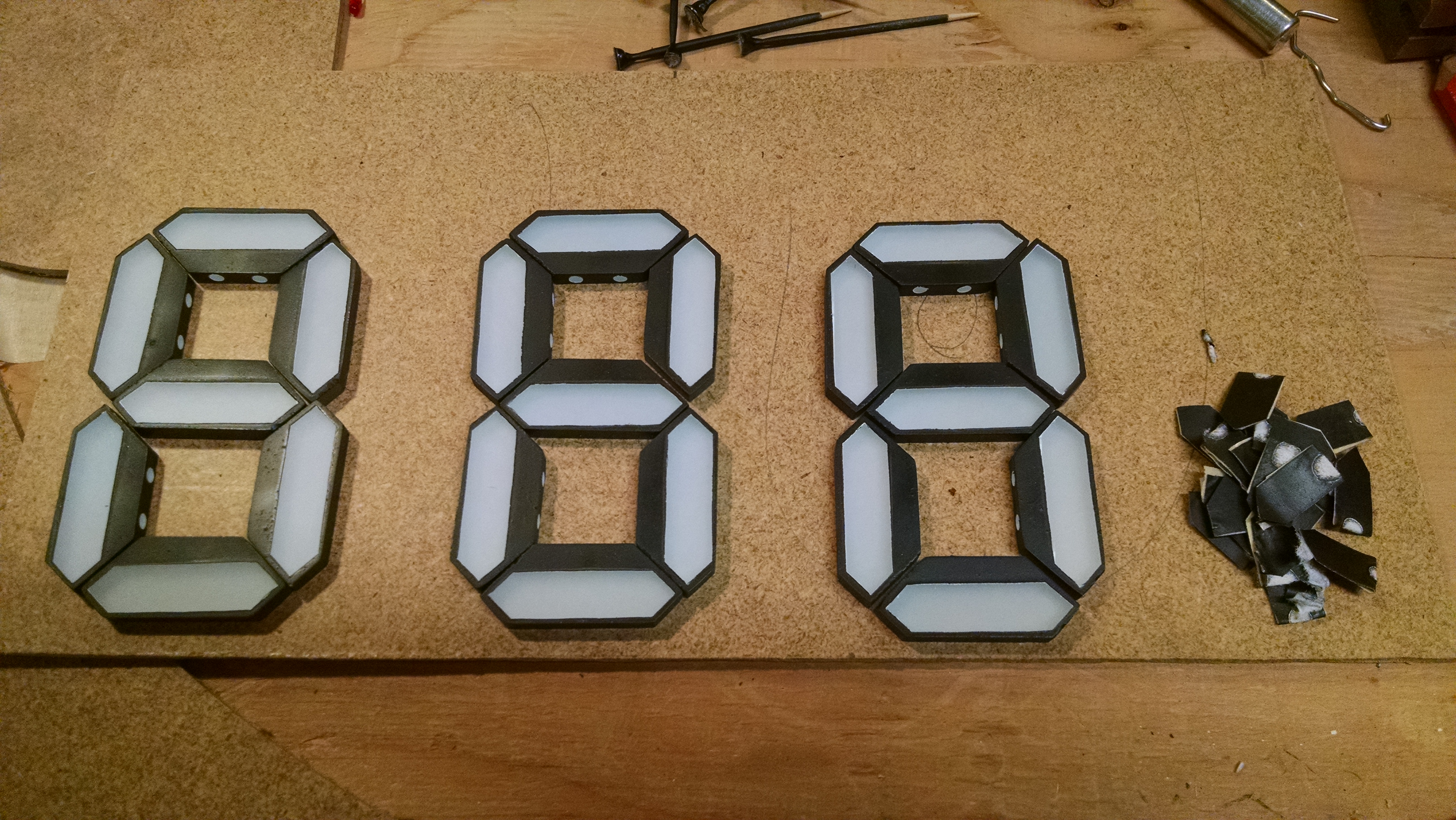
The next step is to get all the pieces attached to the backing board.
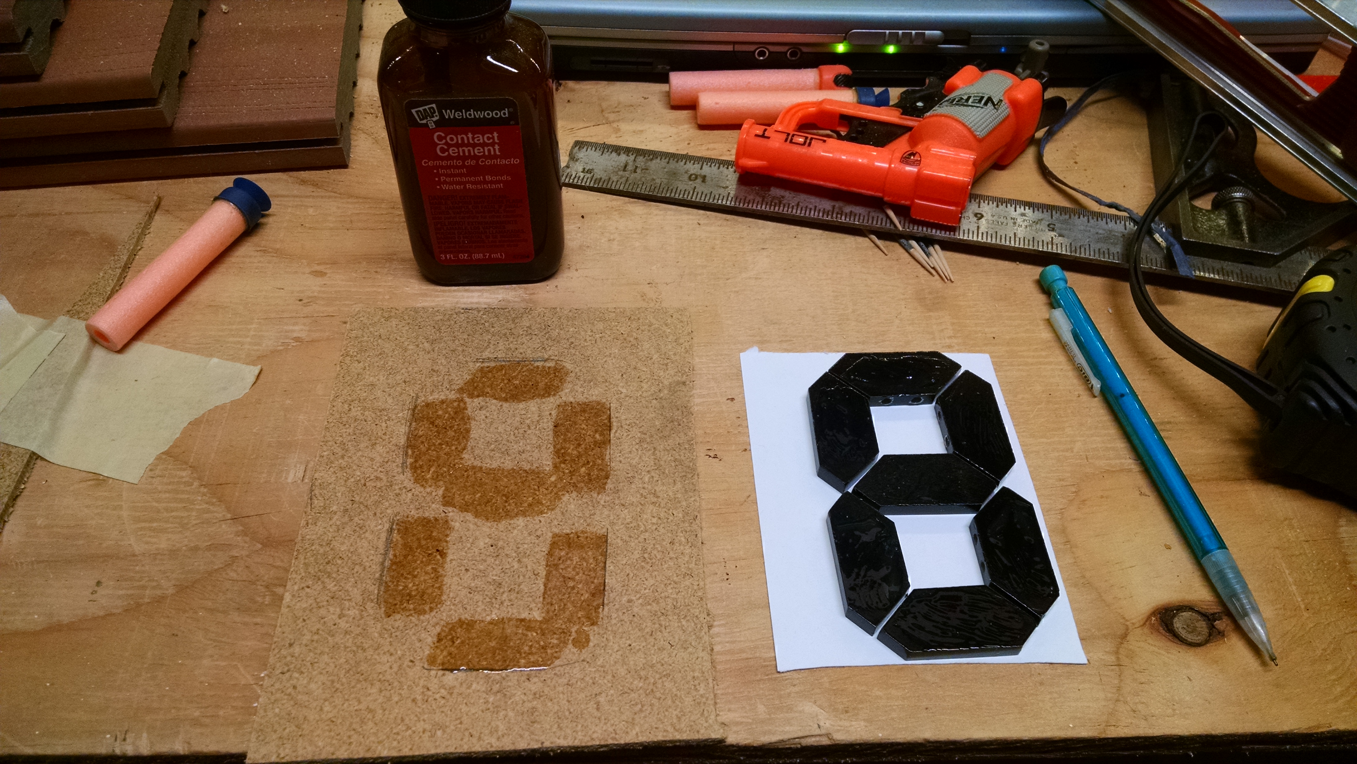
There are probably many ways to do this, but I decided to use contact cement to attach everything, so that drove the next step. Contact cement, as the name implies, adheres on contact. So, there’s not really any opportunity to move pieces around to fine tune them. This means that I needed a way to get the pieces perfectly positioned ahead of time. I did this by printing out the digit outlines (find my template linked here), and cutting holes in the template to align each piece. I also put clear tape over the template so that once a piece was in place, I could stick it to the template.
Once the pieces are in place, apply contact cement to both the segments and the backing board.
A quick note of warning…depending on the spray paint you use, the contact cement may cause the paint to bubble up. When I used a gloss black paint, I didn’t have this issue, but when I used a (cheap) flat black paint, there was a lot of bubbling when I applied the contact cement too thick. I tried placing it anyway, but it looked really bad, so I had to peel up many of the segments, scrape off the bubbled paint, re-paint (both white and black), and stick them down again (using a very thin layer of contact cement to avoid having to repeat a third time).

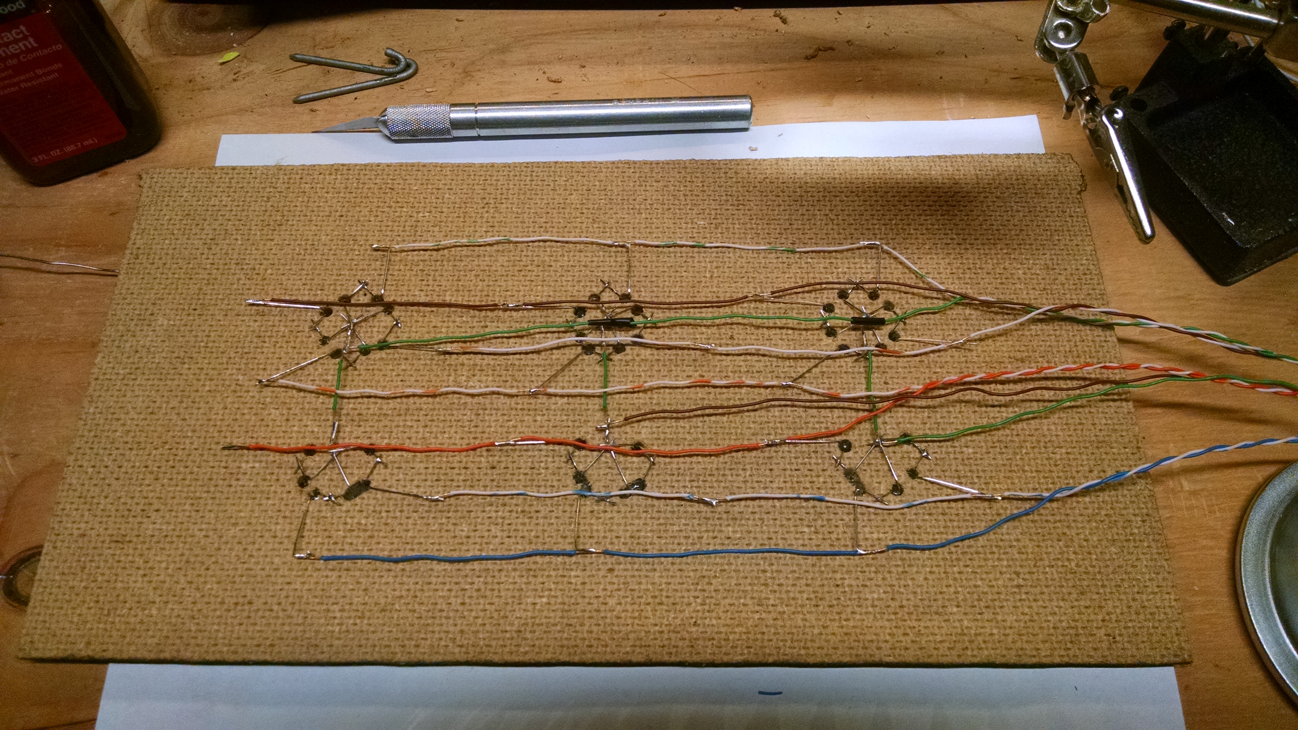
Once you’re happy with how the pieces are attached, drill holes in the backing board for the LED wires to go through, clean up the holes a bit with a blade, bend the LED leads, and hot-glue them in place.
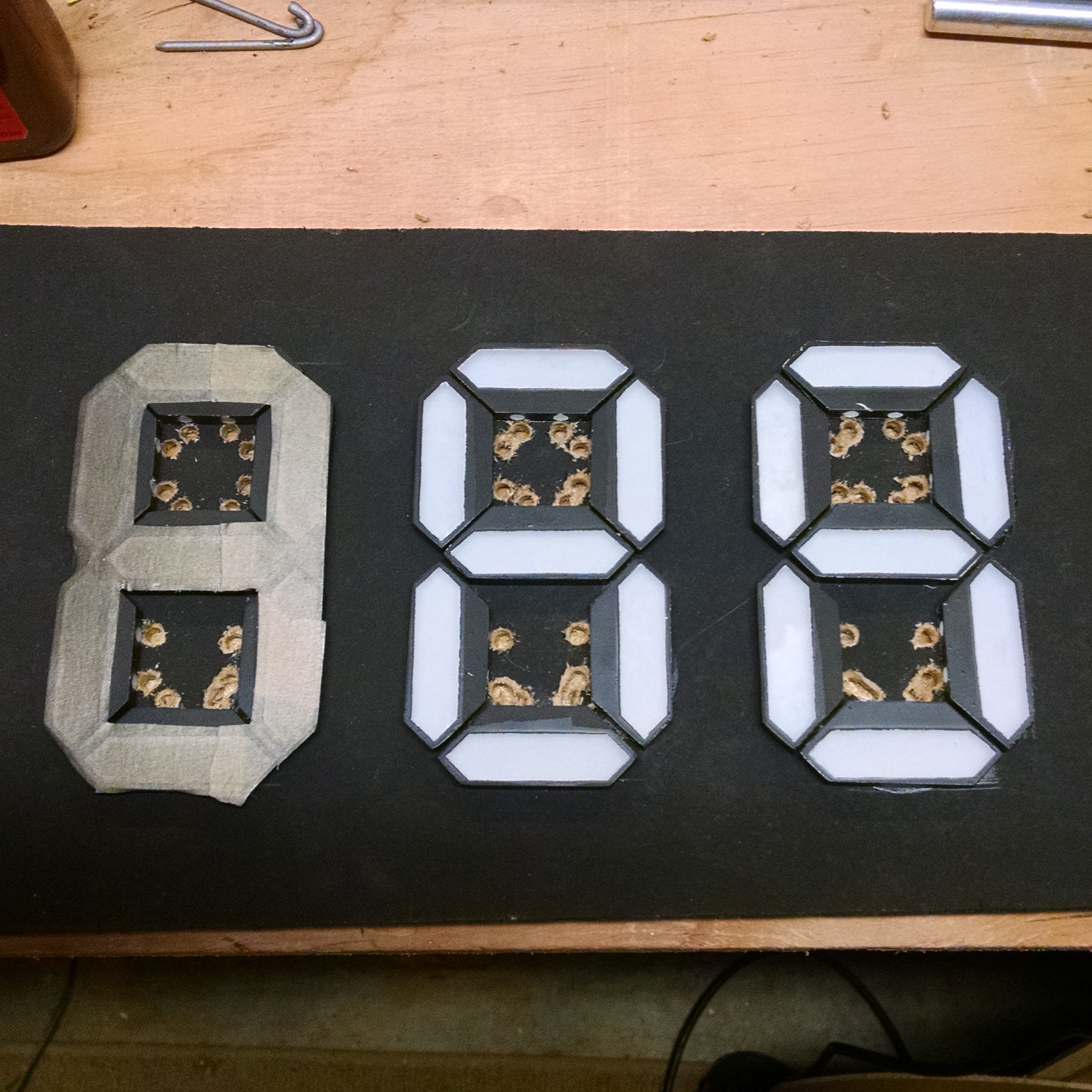
You’ll want to paint over the hot glue, too, otherwise it will light up. I tried using spray paint (masking off the segments again), but it didn’t do a good job of getting into all the nooks & crannies. I ended up using a small paint brush and some acrylic paint.
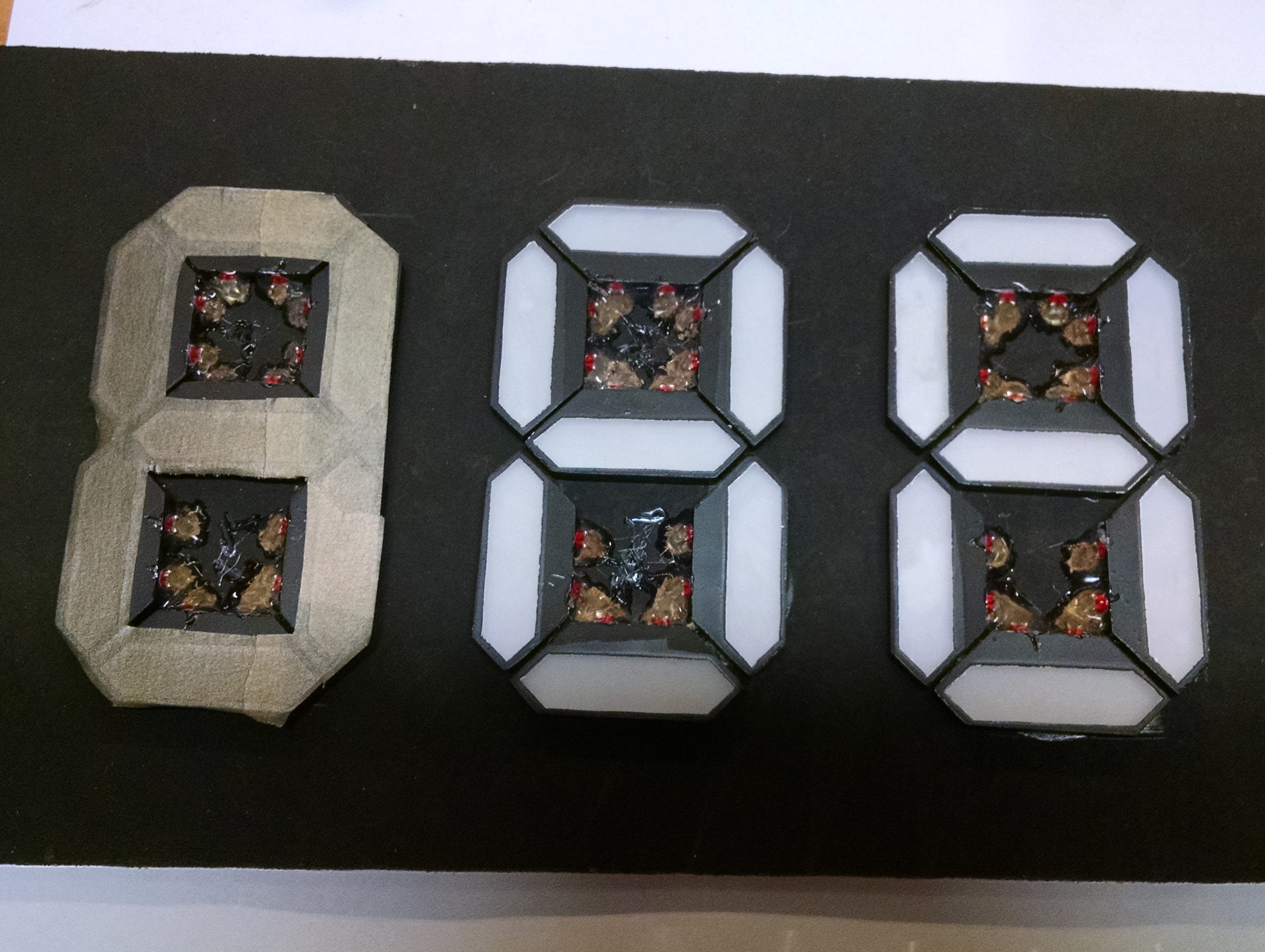
Heat up the soldering iron! First step is to solder adjacent LEDs together (in series). I wanted a common-cathode display (for the MAX7219 LED display driver chip), so I also soldered all the cathodes (the short lead) for each segment together.
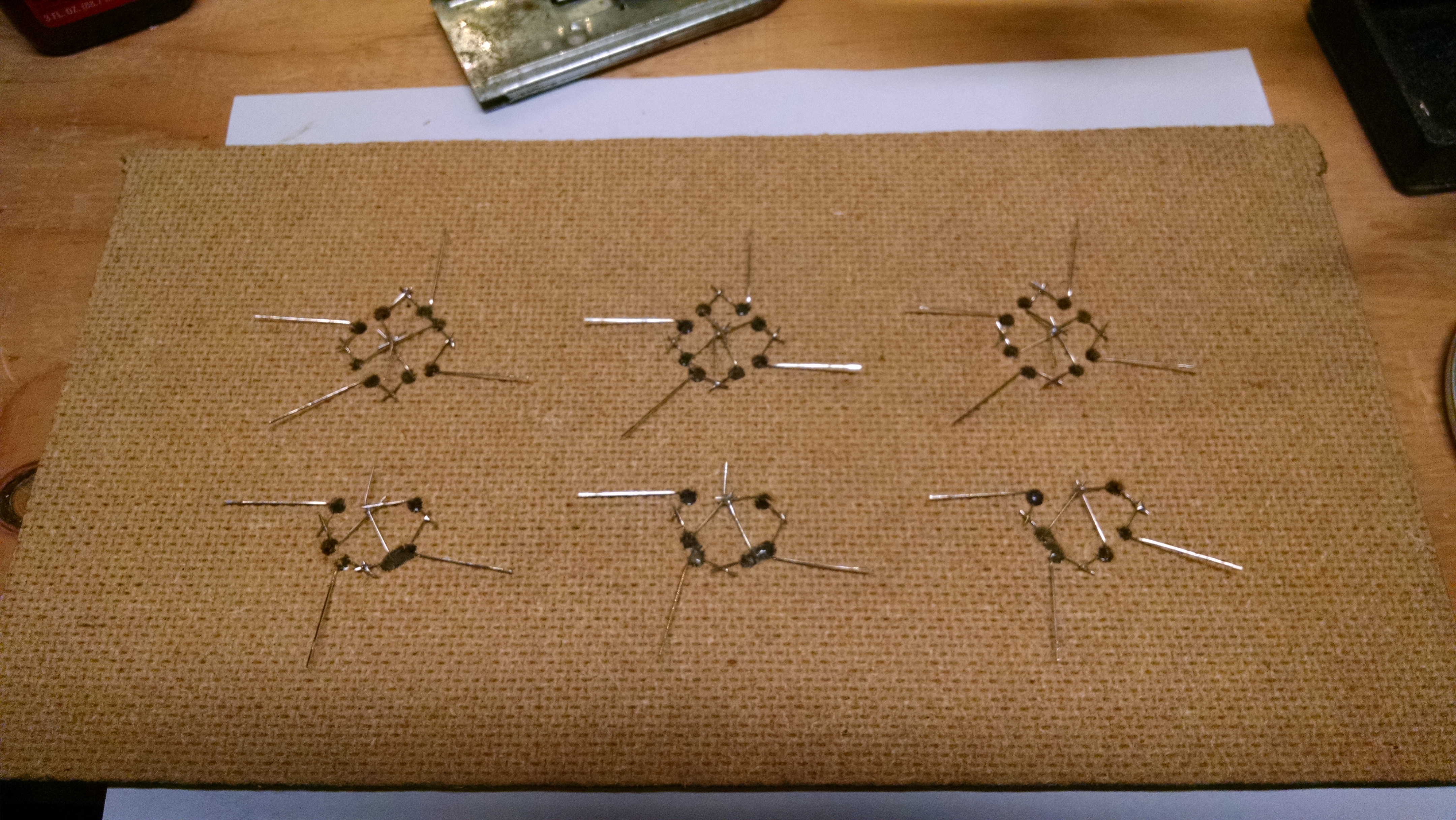
Finally, solder wires connecting the anodes (the long lead) of each segment in the same position together (e.g. all 3 top segments, all 3 middle segments, etc).
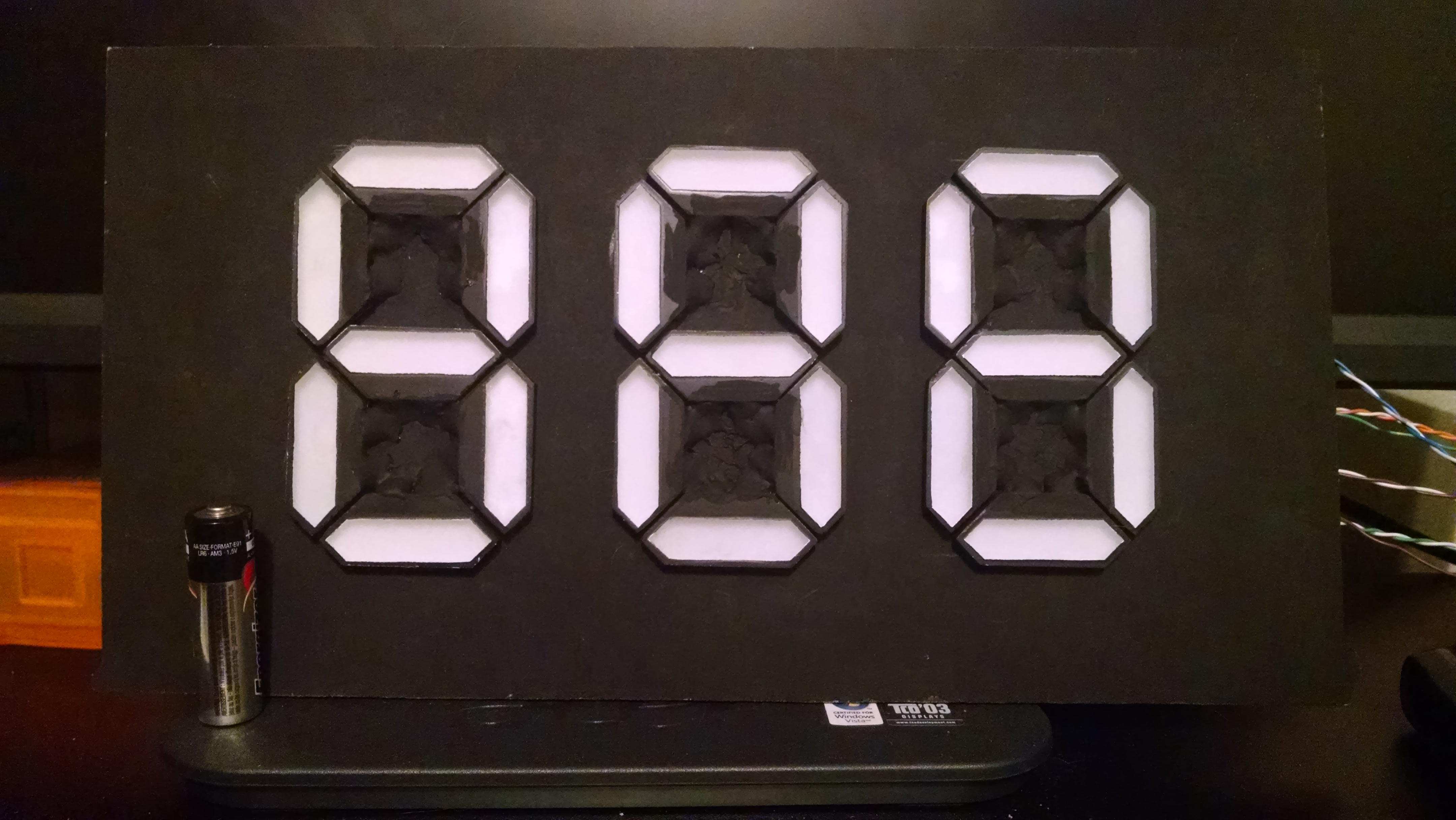
Wire it up and enjoy! (I’ll have a future post about using this display with the MAX7219 LED display driver chip and an ESP8266 microcontroller.)
It looks great in the dark, but in normal lighting, it’s difficult to see which segments are lit. I found that putting a few layers of red cellophane over it helps a lot!
Here it is in my final project (which will get its own writeup eventually…)!


Impressive! great work! How much time did you spend on this? 🙂
Thanks! I don’t think I tallied up the hours…but it was probably longer than I should have spent 😉
Nice project! In terms of your LEDs not being as bright as you would like, have you measured the current that’s being delivered? That 7219 states a source current of between 30 and 45 mA. If the LEDs can handle higher levels (likely, esp since they’re multiplexed), you could add 7 emitter follower transistors between the 7219 and your segments to increase current. (As the drive sink current is at least 320 mA).
Maybe this is more work than changing out your LEDs?!
best, Dan
Thanks! I didn’t directly measure the LED current, but I think I have the appropriate current-setting resistor on the 7219 to drive the current rating of the LEDs. (But I might be able to over-drive them, since they’re only lit at a 1/4th duty cycle.)
In any case, it’s not a problem once I put the red cellophane in front. Without that, it was difficult telling the difference between a white un-lit segment and a pinkish lit segment.
[…] decided to go the DIY route for some 7 segment displays that were several inches tall, but he had some particular requirements. He wanted precisely […]
[…] a couple projects in mind where I want to use a seven-segment display (one of them where I want large digits), but I don’t want to dedicate too many pins to driving the display. Also, writing custom […]
Love the whole project, but I am still confused about the painting, especially the white. Can I assume that you only painted the back side and just used it for reflective purposes? Did you sand both surfaces with the 220 grit or just the side facing up? Finally, how far do the LEDs project into the blocks? Again I assume that you did not want to be able to see the LEDs, just the light, so minimum penetration was desired. Thanks for sharing your project, which looks very professional.
Both sides and the edges are painted white first, but yes, it’s just for reflective purposes.
Both surfaces (and the edges) are sanded. Now that you mention it, I might have been able to get away with only sanding the front side, though.
The whole LED fits in the hole I drilled. In the photo of the drill bit you can see the tape marking how deep I drilled.
Thanks for you comment, glad you liked it!
[…] http://www.mjblythe.com/hacks/2016/06/diy-large-seven-segment-display/ […]