I have a couple projects in mind where I want to use a seven-segment display (one of them where I want large digits), but I don’t want to dedicate too many pins to driving the display. Also, writing custom code to multiplex the digits seemed tedious.
I read about the MAX7219 chip, which lets you drive up to 8 digits over SPI, and it seemed to be just what I was looking for.
You can buy this part from the usual suspects, but I also found that Maxim offers engineering samples.
While I was working on this, the following datasheets were incredibly helpful:
- MAX7219
- the 7-segment display I used
- ATmega168 (I think it used to be here, but that’s a dead link now)
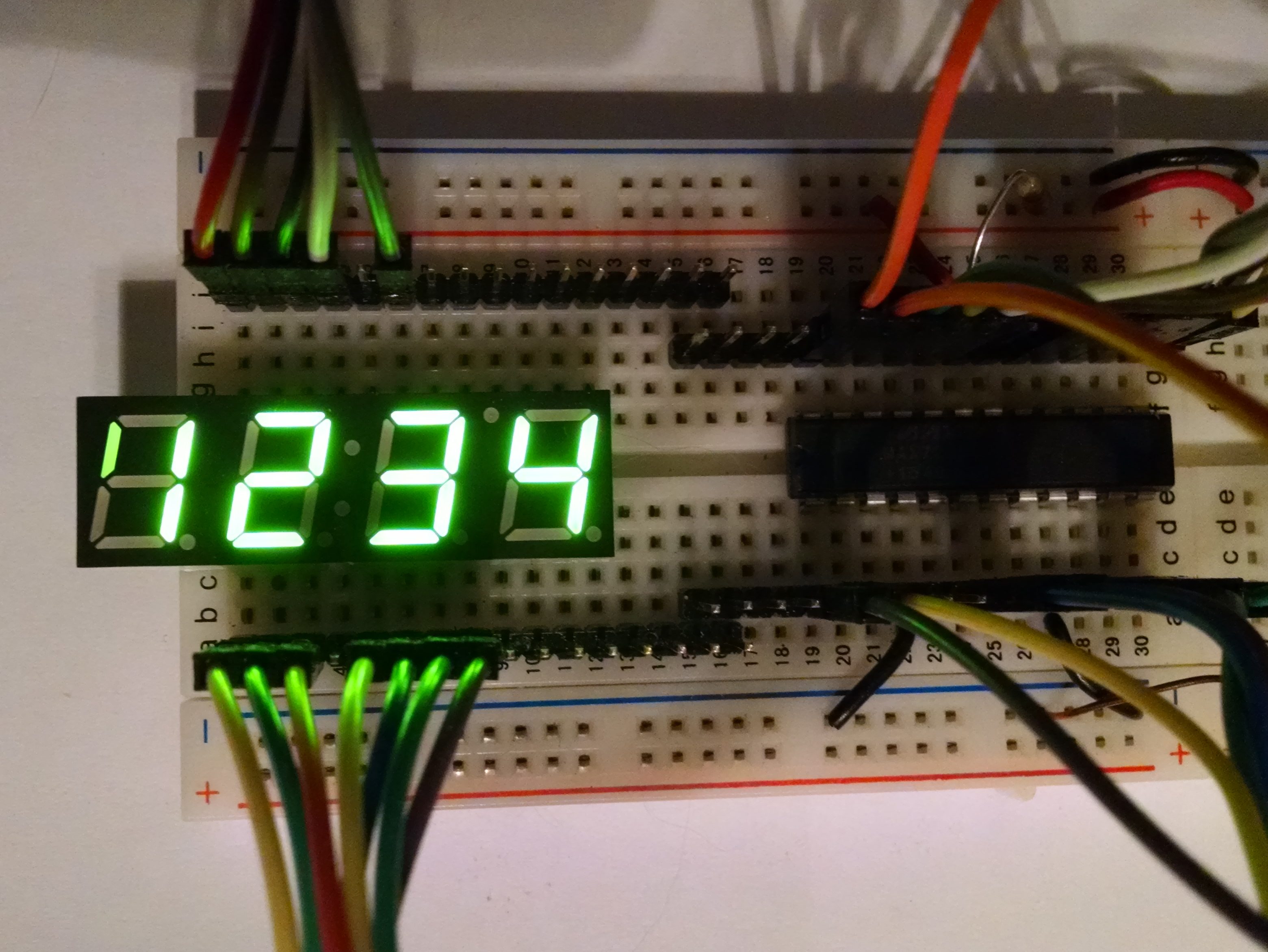
…And here it is, all wired up!
As with any project, this one was fraught with roadblocks, mis-steps, and stumbles that needed to be debugged and addressed.
1) Apparently, I don’t know how to program my board anymore.
When I tried to flash my board, I was greeted by the following wonderfully descriptive error messsage:
Connecting to programmer: .avrdude: butterfly_recv(): programmer is not responding
I hadn’t programmed this board since I updated my computer to Xubuntu 15.10, and something obviously changed. I found this forum thread that indicated I needed to split the avrdude command into two commands, and add a small delay between them:
%-upload: %.hex
        avrdude ${AVRDUDEFLAGS} -e
        sleep 0.1
        avrdude ${AVRDUDEFLAGS} -D -U flash:w:$<:a
That fixed it!
2) It helps to call the code you write
I had coded up a function to configure the SPI block...but it turns out you actually need to call the function in order for it to do anything...duh! While I was trying to figure out where I went wrong, I found this incredibly useful blog post. Of course, none of the tweaks that it lead me to make had any effect until I actually called the function.
3) Infinite loop of resets
Another no-no...don't enable interrupts unless you have the proper ISRs in place, otherwise your chips just resets over & over.
4) It's all zeroes
In retrospect, it makes sense, but at the time I hadn't realized it...all registers on the driver chip initialize to 0. This means that it starts up in shutdown mode. Once you enable that, it's really dim because it's set to the minimum intensity. And once you get it brighter, it doesn't actually show digits because the digit decode mode is disabled!
5) It's all ones
Once I got all the display registers set correctly, I found that non-decode mode (i.e. each bit controls a segment directly) wasn't working...why? Specifically, all the segments were always lit, as if I was loading all-ones into my pattern array. I was trying to write a "spinning" pattern, not all-on.
I worked through lots of stuff...I was convinced that it was a problem with how I was initializing my pattern array:
uint8_t patterns[] =
  { 0b00111110,
    0b01011110,
    0b01101110,
    0b01110110,
    0b01111010,
    0b01111100 };
When I manually initialized the array in main() (i.e. patterns[0] = 0x3e; etc.), it worked as expected, so I was convinced I had something wrong with this code!
I thought maybe it was because I was using C99 syntax, or that the #define I was using for that "0b" syntax was wrong, or something. I don't even remember how many times I changed that piece of code.
No, it's actually that my array initialization doesn't work. After much googling, I finally found the solution on a StackExchange thread (which linked to an avrfreaks thread).
My avr-objcopy command only had -j .text, but it needed -j .text -j .data. Apparently, the array init stuff is in the .data section, which also needs to be copied into the hex file that's loaded.
It's alive!
Finally, after I worked through the last issue, and it worked as intended!
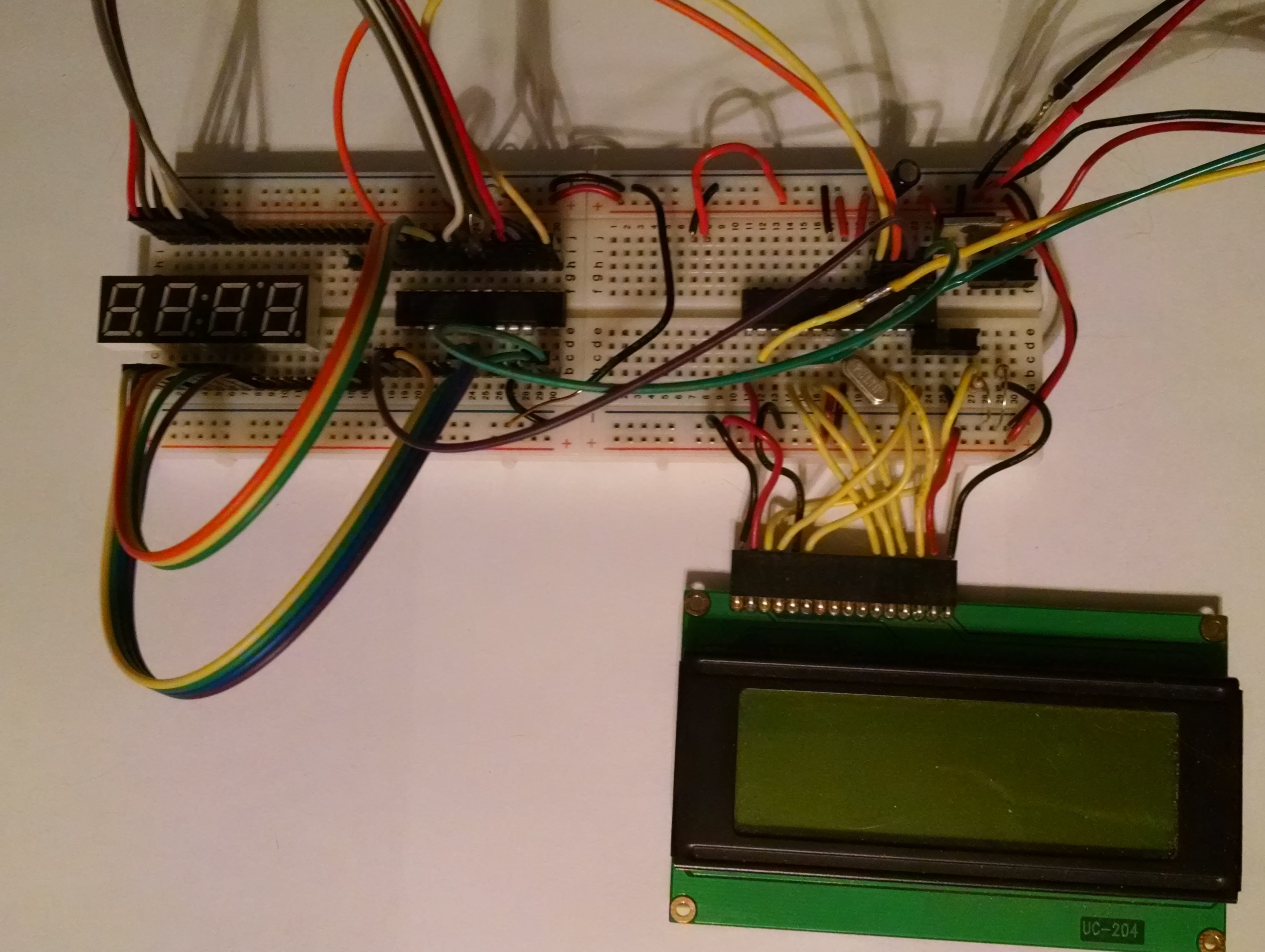
I also ported the code to the ESP8266 (programmed via the Arduino IDE).
The code for both of these microcontrollers can be found on my github page.