
***UPDATE*** I’m going to make some updates to the code, so I’ve modified all the github links below to point to a tagged version. For the latest-and-greatest code, look here.
After I saw this post on hackaday.com about ST Microelectronics giving away STM32F3 Discovery boards for free, I knew I had to have one, but I didn’t really have a specific project in mind for a while. Then, one day I remembered a reverse geocache box that was also featured on hackaday, and realized that I could do something similar. The F3 Discover board includes a 3-axis accelerometer & 3-axis gyroscope, so instead of using GPS, I would only have the box open when it was rotated through the correct sequence of orientations.
For those who don’t want to read the whole post below, the code is posted on my github repository. Also, those looking for photos should skip to the last half of the post.
Since I had ordered the free sample in late November, I figured that I’d have enough time to make this puzzle box as a Christmas gift for my wife. Unfortunately, it didn’t arrive until the day that we celebrated our early Christmas (before we travelled to see our families). Not quite enough time to throw it together… Fortunately, that just meant that I had more time to put something together by the next gift-giving opportunity…St. Valentine’s day.
Materials
- Pre-assembled box
- Servo motor
- Piezoelectric speaker
- Red, diffused 3mm LEDs
- Female/Female jumper wires (I also got some male headers for versatility)
- Battery holder
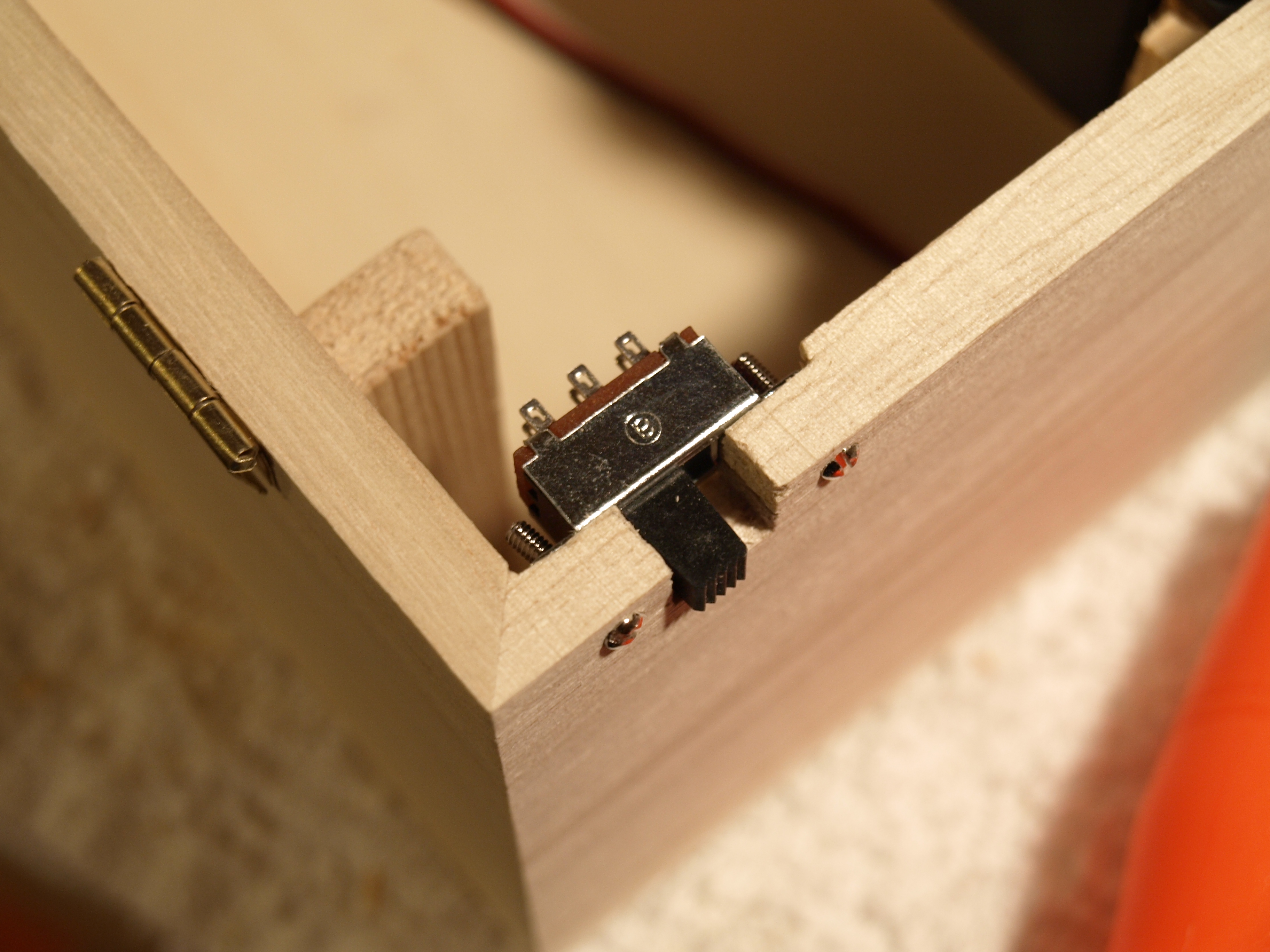
- On/Off Switch
- Micro-switch
- Misc (scrap wood, steel wire, glue, etc.)
The box I got was from Michael’s, similar to this one, except that the cover had a rectangular cut-out with a wire mesh in it that I removed. I also bought some unfinished birch plywood to cover the cut-out. In the end, I think having this cut-out made it much easier to get the locking mechanism working, so I’d recommend it.
The servo doesn’t have to be anything special…I just went to my local hobby store and asked for the cheapest one they sold.
Likewise, the piezo speaker isn’t anything special either. I happened to have a spare that used to be a “PC speaker”, and it worked well because it was already connected to a 0.1-inch female header.
The On-Off switch that I used was one that I already had from Radio Shack or something. It was a 2-pole 2-throw switch, which was overkill, but it worked fine.
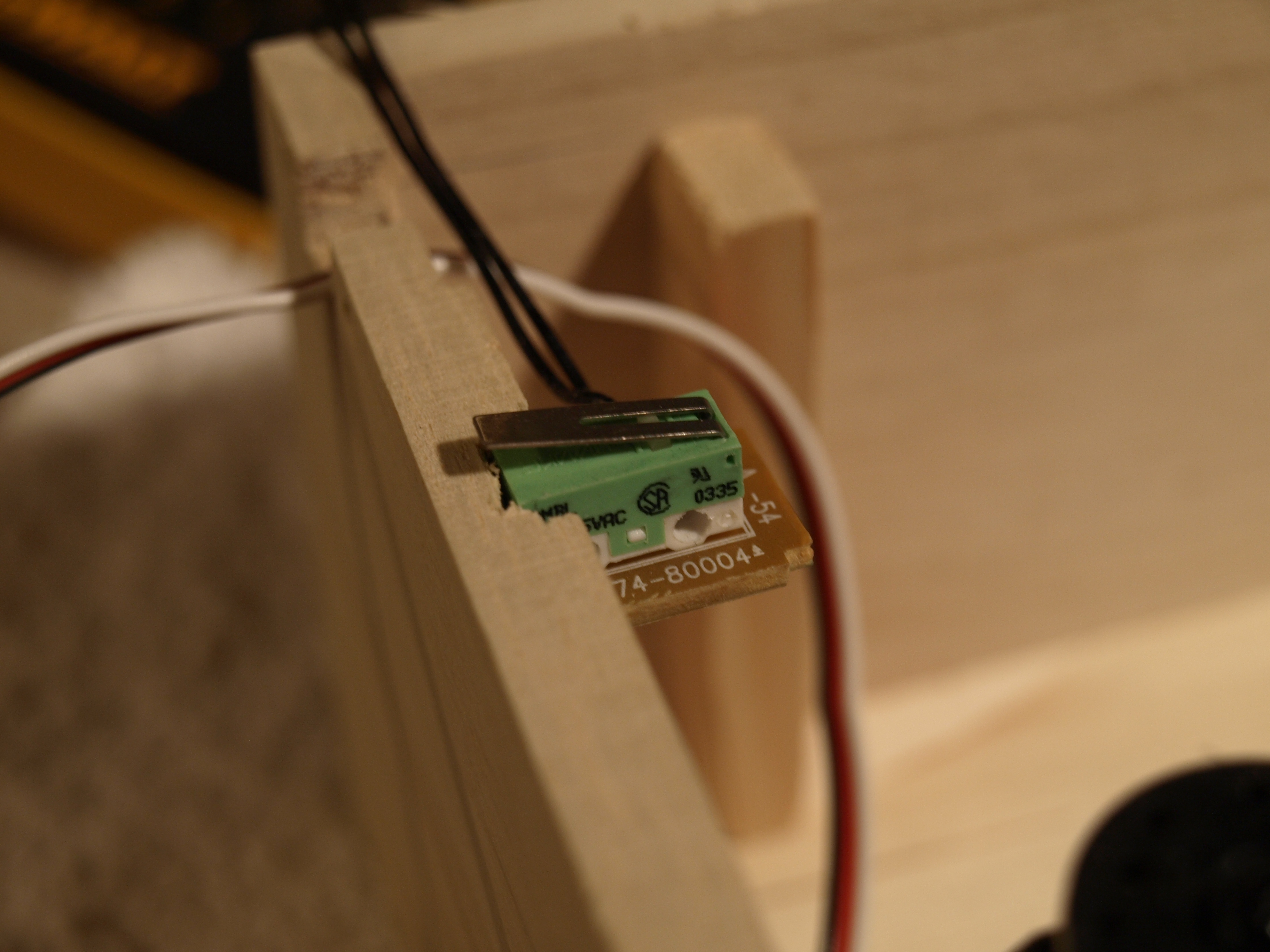
I used a micro-switch from a junked HP printer to sense when the box is open or closed. It also had a 0.1-inch female header, which was convenient.
Servo
I figured the easiest way to latch the box would be to have a servo motor drive some sort of a sliding mechanism, so my first step was to get the servo working with the Discovery board. I hadn’t used a servo on a project in a long time, so I had to look up how to control it. Fortunately, wikipedia has an article on servo control, with this helpful graphic:

In order to achieve this, I decided to use some easy math. I set up a Timer 3 to do PWM and to have a clock divider of 72 (with a 72MHz clock, each timer increment would be 1 μs), a period of 20,000 counts (20 ms), and then controlled the pulse width by setting a compare register to a value between 1000 (1 ms) and 2000 (2 ms). I found, however, that the rotation difference between a 1ms and 2 ms pulse was only about 90 degrees. In order to get about 180 degrees of rotation, I needed 0.55 ms and 2.3 ms pulses.
My servo control code is here.
I had considered trying to get as much accuracy as possible from the servo by finding the lowest clock divider that wouldn’t overflow the 16-bit timer in 20 ms, but the extra accuracy was unnecessary. Also, when I tried to figure out that math, it was too late at night for me to make sense of it.
I thought it might be an issue that the servo was powered by 5V, but the signalling from the STM32F3 was only 3V. This turned out to be fine. I was also worried about powering the servo, but my USB hub provided enough power to the servo during the prototype & debugging phase before I moved over to using a battery pack.
Buzzer
I figured an audible beep would be a good way to provide feedback to the puzzle-solver about whether they had made a correct move. This feedback would have to indicate both good and bad moves, however, so I decided to use different frequencies. I settled on having a “bad” beep be 200 Hz, and a “good” beep be 800 Hz. Similar to the servo, I used a timer in PWM mode to generate these tones. For my own sanity, I used the same clock divider of 72, and set the period and compare register to 1250 & 625 for a “good” beep, and 5000 and 2500 for a “bad” beep.
I also wanted the beep to only persist for a short time. In order to do this, I used the SysTick timer, set up to generate an interrupt every 10 ms. Whenever I wanted a beep, I enabled the PWM timer, and set a counter to 25. Every 10 ms, the SysTick handler would decrement this counter, and when it reached 0, it would disable the timer again. This would result in a beep of about 250 ms (i.e. 1/4 second). Of course, when I later coded up the puzzle game itself, a “bad” beep would be triggered as long as the box was in the wrong position, so a “bad” beep could be much longer than 250 ms.
The buzzer control code is here.
When I was developing things, I thought the beeper sounded plenty loud, but I found that the sound was much quieter than I expected once the buzzer was in the box. I haven’t addressed this yet, but I’d first try to make the buzzer louder by having it connected to complimentary outputs from the timer. This way, the buzzer would have a 6 V peak-to-peak signal, instead of 3 V peak-to-peak. Failing that, I could drill some holes in one side of the box…essentially a simple speaker grille.
LEDs
I also wanted a way for the puzzle solver to get back to the previous point of failure quickly, and LED indications fit this nicely. For early development, I just used the 8 LEDs on the Discovery board itself. After I had made the box’s cover with the LEDs arranged in a heart, I modified the code from ST to control those pins instead.
I had originally planned on using 6 different indications:
- Blink the top half of the heart (or circle, while developing)
- Blink the bottom half
- Blink the left side
- Blink the right side
- Sequence the LEDs in a clockwise rotation
- Sequence the LEDs in a counter-clockwise rotation
I quickly determined that this would lead to ambiguous indications. Would blinking half mean that side should be up? down? a rotation in that direction? After consulting with a co-worker (thanks, Logan!), I settled on these indications:
- Sequence LEDs from top-to-bottom
- Sequence LEDs from bottom-to-top
- Sequence LEDs from left-to-right
- Sequence LEDs from right-to-left
- Sequence LEDs clockwise
- Sequence LEDs counter-clockwise
Here’s what each of those looks like:
Like the beep length, it didn’t make sense to handle this LED sequencing in the main program loop, so it is also handled during the SysTick interrupt. The code that controls the LEDs is here.
Selecting Difficulty & Gyroscope
I had decided fairly early that I wanted to implement different difficulty levels, mostly by changing what feedback was given to the puzzle-solver. I decided on the following levels:
- Easy – audible feedback & the LEDs would always indicate the direction the box needed to be turned
- Medium – audible feedback, but the LEDs would only indicate directions to get you back to your point of furthest progress
- Hard – audible feedback only, no LEDs at all
- Impossible – no audible or LED feedback. If the puzzle is successfully completed, the box still opens, but when a mistake is made, nothing happens.
I considered adding a button to select difficulty, but then it dawned on me that I could just use the on-board gyroscope to have the puzzle-solver literally dial in their difficulty by rotating the box around the vertical axis. If the box is turned 1/8 turn, the very bottom of the heart lights up, and easy is selected. 1/4 turn lights up the bottom half of the heart and medium is selected. 3/8 turn light up more, and hard is selected. At 1/2 turn, the heart is fully illuminated, and impossible difficulty is selected. Once the box is rotated back to the original position (that is, back 1/8, 1/4, 3/8, or 1/2 turn), then the puzzle starts in earnest. Here are the various illumination levels for the difficulties:
Implementing the gyroscope code was fairly straightforward, given the example code from the Discover board firmware download. The one problem that I had to solve was that the gyroscope would output values as a rotational velocity in degrees per second, but I wanted the rotational position. In order to perform the integration necessary to get position from velocity, I just had the SysTick interrupt handler estimate the positional difference from the last interrupt call. I assumed that the velocity (returned by GyroReadAngRate()) was constant in the interval between SysTick calls (10ms), so angular position would increase or decrease by .01 * degPerSec. I could have gotten much more sophisticated (and hopefully accurate), but this worked well enough.
The code for reading data & integrating position from the gyroscope is here.
Puzzle program
At this point, most of the individual pieces were working, so I started coding up the puzzle implementation itself.
The main() function has the program loop, which essentially implements a finite-state machine. When we’re in the STATE_PUZZLE state, we call DoPuzzle() which reads the accelerometers. If the acceleration is 6 times greater in one direction ( which corresponds to being within about 10 degrees of vertical), then it calls HandleNewDir(direction), which is where the interesting things actually happen.
In the simplest version of HandleNewDir(direction), we compare the direction passed in with what we know is supposed to be the next direction in the sequence. The sequence is stored in DirList, and DirPos indexes into this list to keep track of our progress. If the 2 compare correctly, then DirPos is incremented, and we trigger a “good” beep. If the 2 directions miscompare, then we reset DirPos to 0 and trigger a “bad” beep. The other case we have to handle is when the puzzle solver holds the box in place after hitting the next direction in the sequence. This is tracked by LastDir, and when the new direction is equal to LastDir, we do nothing.
As I added features to the puzzle box, HandleNewDir(direction) gets more complex with
- Tracking the furthest progress
- Conditionally emitting beeps based on the difficulty setting
- Conditionally setting the LED indication based on progress & difficulty
Of course, aside from actually doing the puzzle, we have to determine if the box is already open, and if not, then let the puzzle-solver select their difficulty (handled by the DoGyro() function), and we have to know what to do when the puzzle has been won. This is the reason for the rest of the finite-state machine in main().
All of this code can be found here.
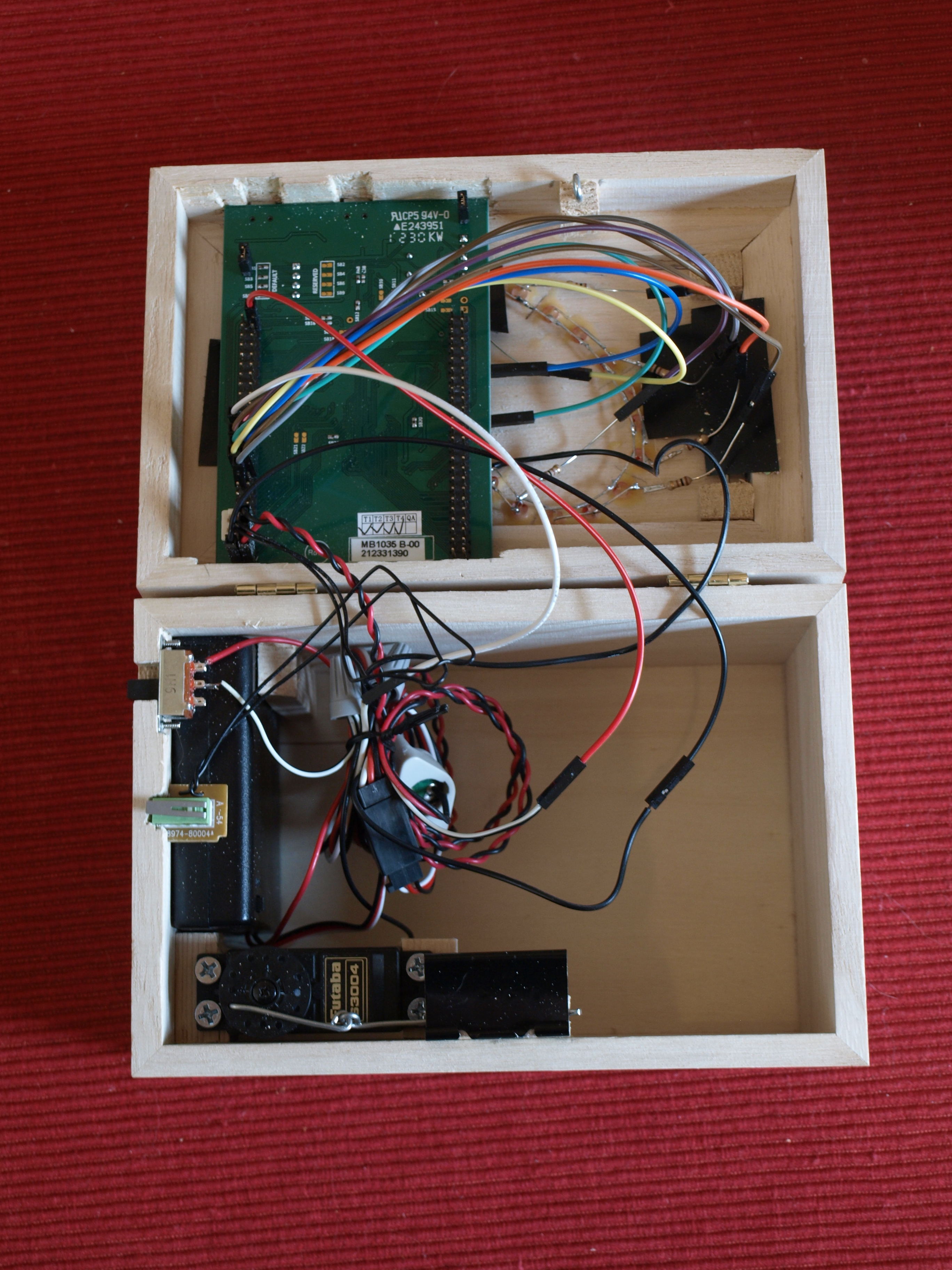
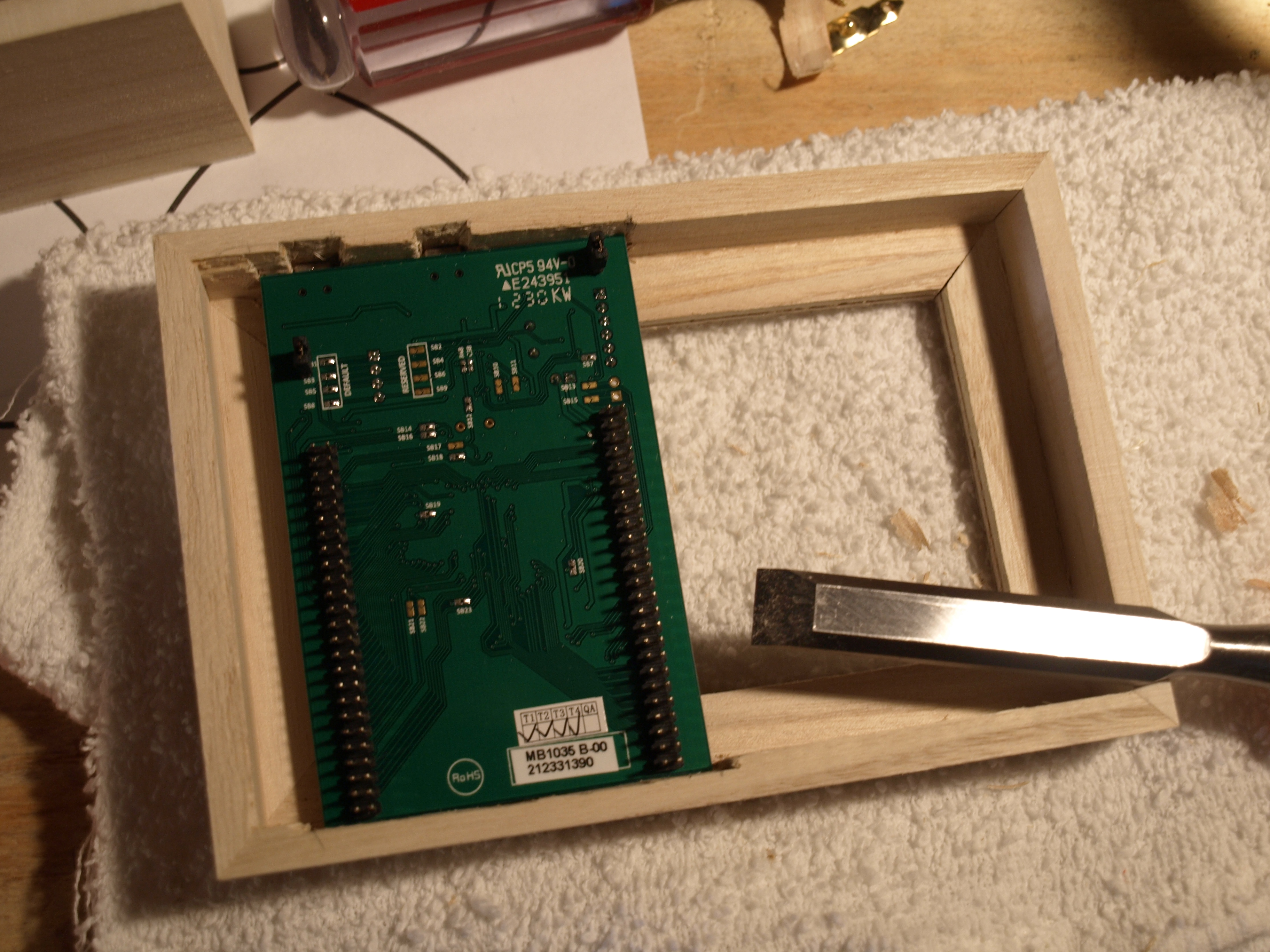
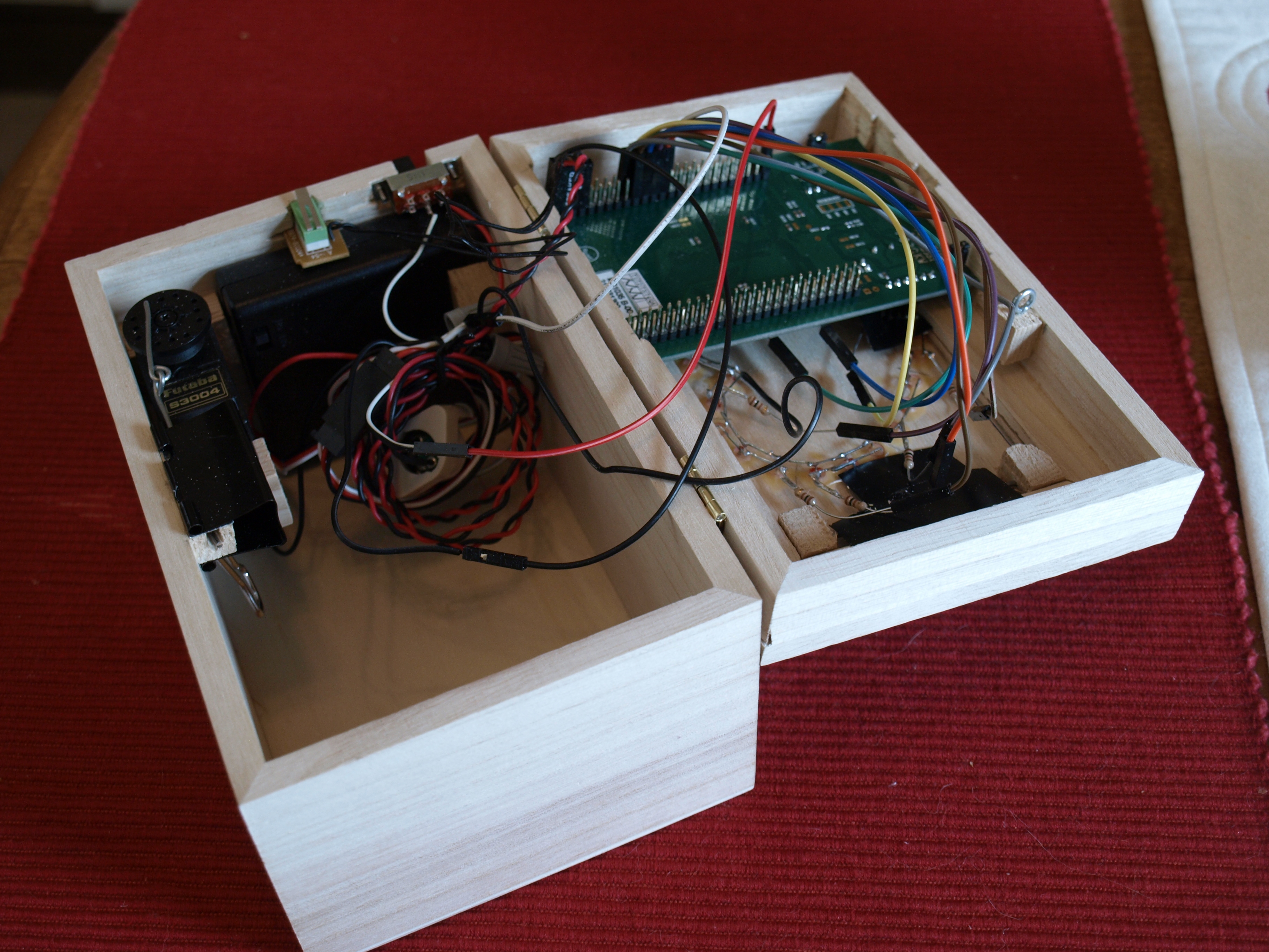
Physical Construction
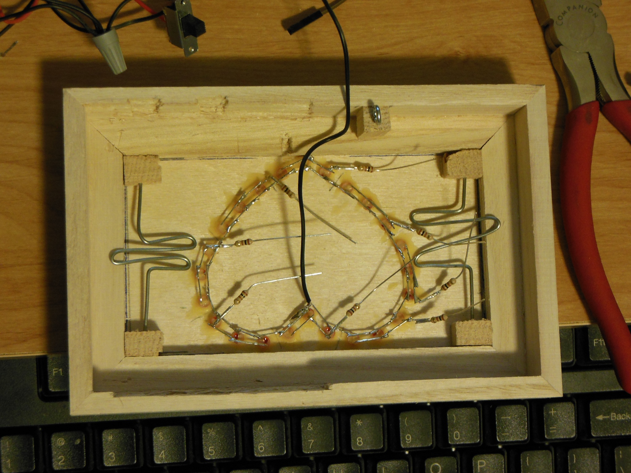
Even though navigating the register maps of the STM32F3 to set up all of the previous functionality was unfamiliar territory, it didn’t cause me the same anxiety as figuring out how to pack & secure everything inside the box. I’m an Electrical & Computer Engineer after all, not a Mechanical Engineer. You can see from the photo below how I fit everything in (and left room for some real Valentine’s day gifts, too!), but I’ll call attention to a couple of things I struggled with.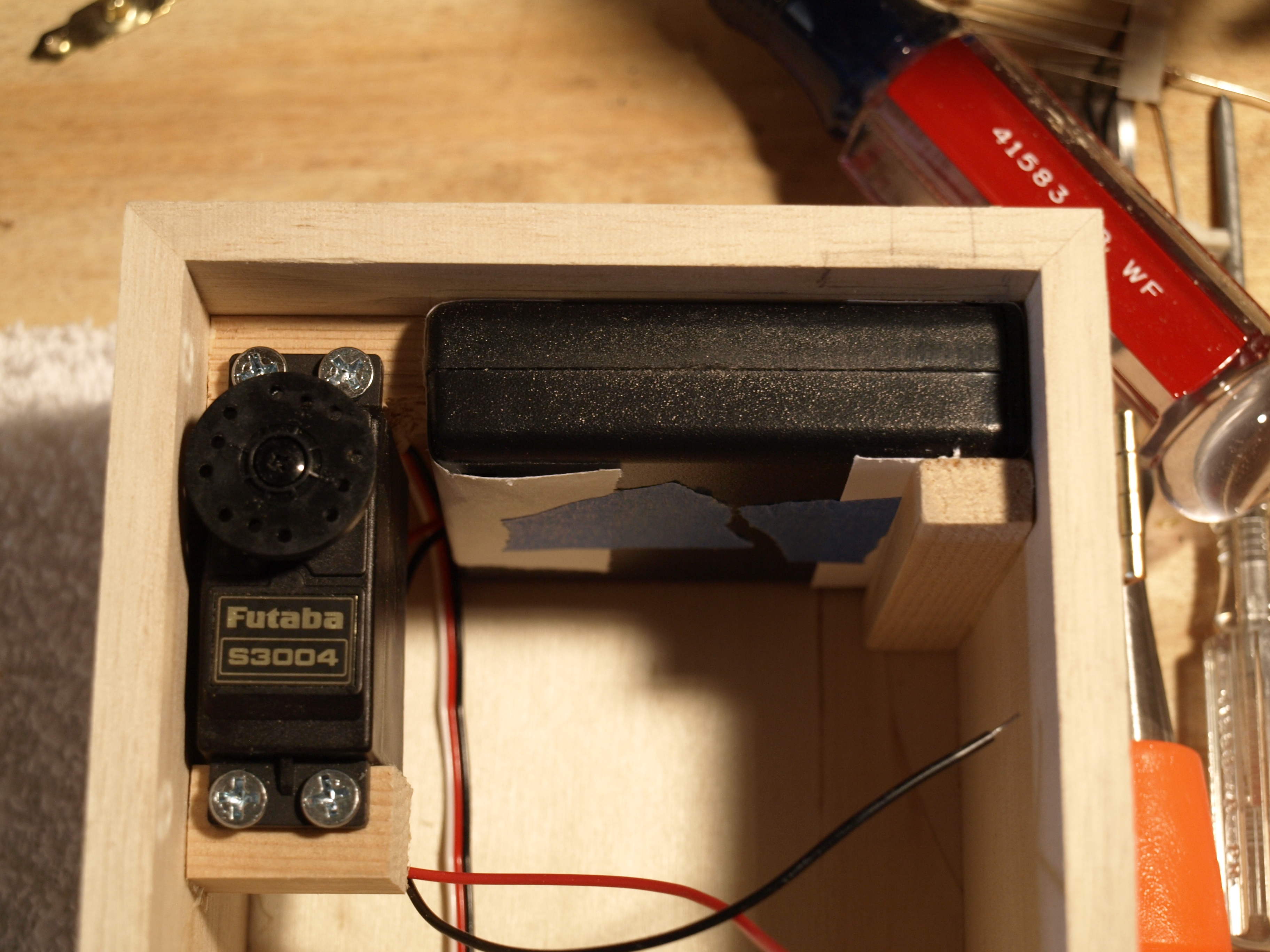
LED heart
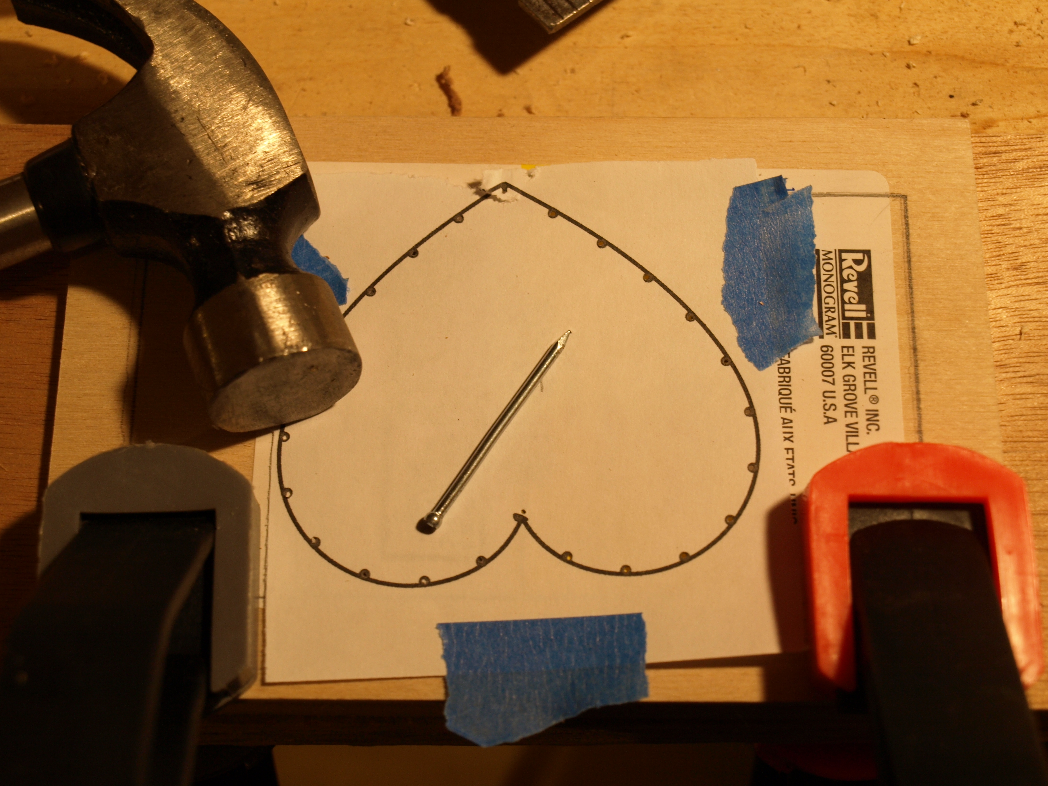
I didn’t struggle with this so much, but I thought I had a clever solution to making the heart turn out well. First, I found a nice SVG image of a heart, then I used Inkscape to place 24 dots evenly around the path of the heart. Next, I put this image into Scribus & resized it to 3 different heights that were close to the dimension I was looking for. (All of these files appear here, here, and here.) After I printed this and determined which height would work best, I transferred the dots to the plywood by hammering each one with a nail a little bit to leave a dent.
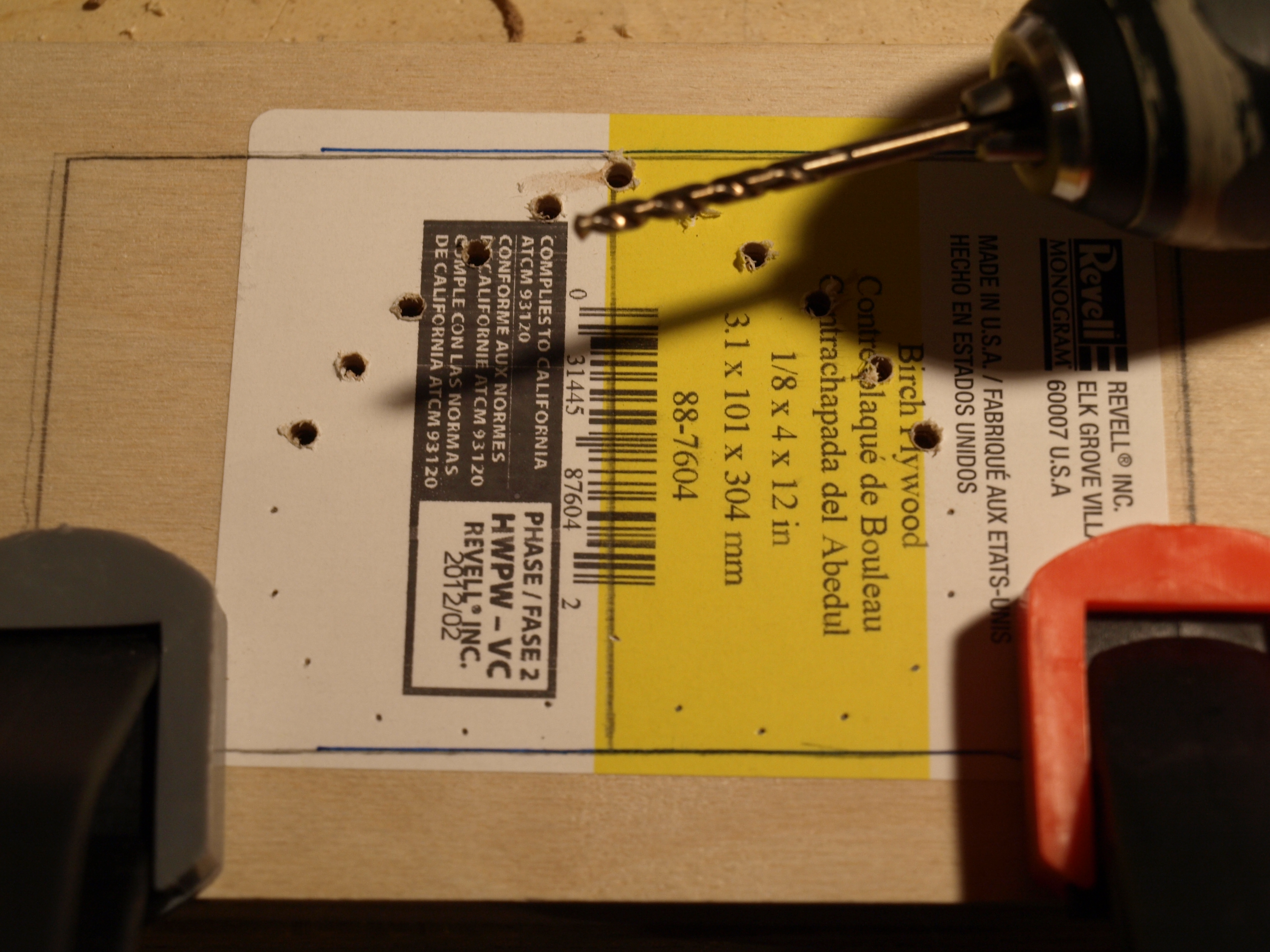
Once all the points for LEDs were marked, I drilled the holes for the LEDs. In order to make a clean cut, I drilled “good side” down, and clamped it to another piece of wood, which I also drilled into. I first tried drilling a 7/64 inch (2.78 mm) hole, expecting that it would be just a little snug on the 3 mm LEDs, but it was too small to get the LED in at all. I had to use a 1/8 inch (3.18 mm) drill bit instead. the LEDs fit fine, but they weren’t very snug at all.
I tried using wood glue to hold them in place, but found that wood glue didn’t adhere to the plastic cap of the LED very well at all. I ended up basically covering the entire back side of each LED with the glue to hold it in place.
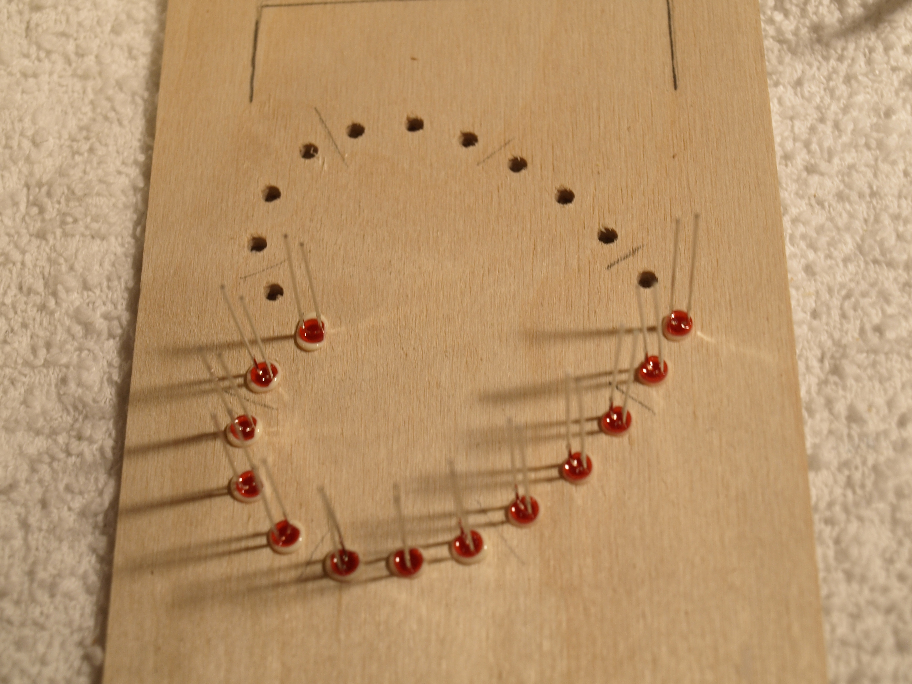

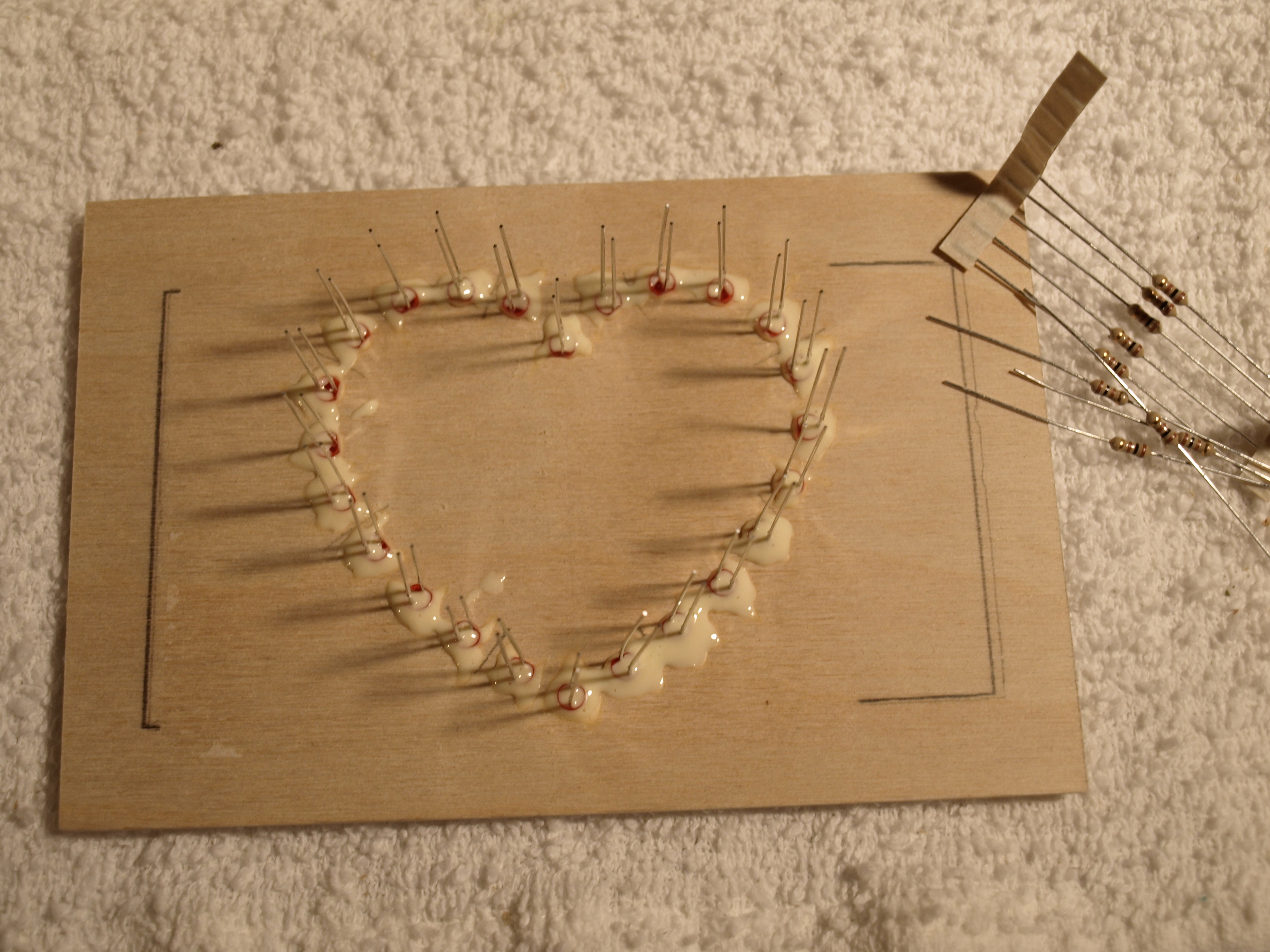
Once the glue dried, things were held in place pretty well. Soldering everything together was pretty straightforward from that point.
Latching mechanism
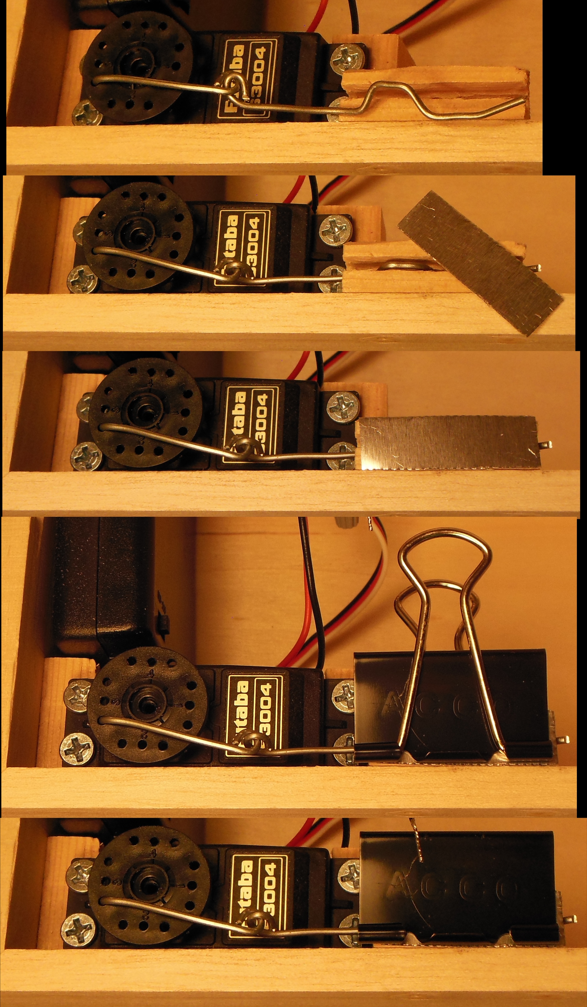
In my first revision, I had simply drilled a hole through a piece of wood for a steel wire to go through. The servo pushed this wire, and it would hook through an eye hook on the lid. In order for the lid to securely latch, this wire had to be near the bottom of the hook.
However, if the wire was too far down, it would hit the hook instead of going through. In this case, the servo would just bend the wire, and it wouldn’t work until I straightened things again by hand. I tried bending the tip of the wire upwards slightly, but 2 things prevented this from being very effective. First, I couldn’t bend the wire very much since it still had to slide back into the hole drilled into the wooden block, and there was only about 0.05 inches of leeway. Second, the wire was free to rotate in the block of wood, so if the tip was bent “up”, it might flop over to one side or the other on the next movement. This video shows the function and failure of that first design:
I solved this by cutting a slit in the block of wood instead of simply a hole. This way, I could bend the latching wire in such a way that it couldn’t rotate in the hole, and and “upwards” bend would remain upwards. Also, this allowed me to bend the tip upwards much more since I only had to fit back into a slit, and not into a hole. This new design worked much better:
Attaching the cover
I had originally planned to glue the plywood with the LEDs to the lid of the box, but after the trouble I had with the latching mechanism, I didn’t want to do anything so permanent. I decided to glue little blocks of wood onto the plywood that fit snugly against the 4 corners of the opening in the lid. Before gluing them, I had drilled holes in each block so that I could insert some retaining clips I bent out of steel wire to hold the plywood cover in place. Now, if something gets messed up, I can remove the retaining clips on the cover again and use the opening in the lid to debug it.
Conclusion
When I gave it to my wife on Valentine’s day, she thought it was pretty awesome. Even after she had opened it (on medium difficulty), she played with it for long enough that she had memorized the hard-coded sequence of orientations. She also liked the gifts I had stowed inside (a candle, some candies, and some romantic “coupons”).
When she was playing with it, though, I did notice a few things that I could have improved. First, when an incorrect move was made to topside-up, the box would emit a high beep. This was because even though it was an incorrect move, it was the first correct move in the re-try. I should tweak the code to emit a longer low beep to signal the failure.
I already mentioned above that once the box was closed, the beeper was too quiet. This shows on the demonstration video, too.
I’d also improve my wire management. When playing with the box, I had to be very careful not to close the lid on a wire. The lid would still lock in place, but I think it has loosened.
Finally, I want to improve the program to generate a new random sequence every time. The impossible difficulty is somewhat defeated now that my wife has memorized the sequence.


Nice use of a servo to lock things up! Wire management always seems to be a problem with “hacked” projects. But hey, as long as it works!
Poor wiring is a pet peeve of mine at work, but I get paid to actually act professionally there…
[…] Here’s a new take on a gift box which has been locked from the inside. I doesn’t rely on GPS coordinates or a real-time clock to unfasten the latch. Instead, the box itself acts as a puzzle. You follow the visual and audio clues, turning the box along three axes in order to input the unlock code. […]
[…] of each coupon!) Anyway, for him the real fun was watching me figure out the puzzle! He’s blogged all about how he made it… but for those of us who are less technical and don’t understand anything he blogs […]
[…] developing my Valentine’s day puzzle box, I found myself really wanting to single-step through some code to figure out where things were […]